Aperture Synthesis with VLA and ALMA Radio Telescope Arrays

Requires a Wolfram Notebook System
Interact on desktop, mobile and cloud with the free Wolfram Player or other Wolfram Language products.
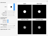
How does a radio-frequency telescope array such as the VLA (Very Large Array, in New Mexico) or ALMA (Atacama Large Millimeter Array, in Chile) form an image, here of a pair of interacting galaxies? As Earth rotates, the object:array viewing geometry changes to record different Fourier coefficients of spatial frequencies  and
and  that make up an image. Each pairing of dish antennas produces a single curved track in the
  -
- plane. Although many coefficients are not measured by the sparse array of dishes, enough are recorded to produce a reasonable fidelity image whenever structure is not over-resolved. The three pictures, from left to right, are: the
  -
- plane Fourier coefficients mapped out by Earth rotation during the total exposure "track", the object being observed, and the result of imaging with the linked array of radio dishes. Dishes in both radio telescopes are moved every few months to pads of different separation, allowing the telescope to "zoom" in or out to cover different fields of view on the sky at different angular resolutions.
Contributed by: Gerald Cecil (March 2011)
Open content licensed under CC BY-NC-SA
Snapshots
Details
Duration: the integration time in minutes. Once every 20 minutes the integration is interrupted to move to a nearby calibration target.
VLA (≤ 0) or ALMA:  selects the A, B, C, D distribution of VLA unit dishes, respectively, while > 0 selects ALMA dish distributions. Image detail decreases from
  or
or  , then increases. Sensitivity to smooth structure does the opposite.
 : declination, latitude-analog coordinate of the astronomical target. The unit dishes can point to within
  of the horizon for the VLA and
  for ALMA. The VLA is at
  N while ALMA is at
  S.
S.
Information on the VLA and international ALMA telescopes can be found at the U.S. National Radio Astronomy Observatory, http://www.nrao.edu. The default image is a grayscale of Messier 51 from the U.S. National Optical Astronomy Observatories (NOAO), http://www.noao.edu/image_gallery/html/im0653.html, used with permission from T. A. Rector and Monica Ramirez/NOAO/AURA/NSF.
Cool thing to try: replace "object" with your own {512,512} 8-bit deep image and run the program.
Snapshot 1: VLA integrating for 100 minutes in configuration -3 (A array), the narrowest angle and highest resolution, target at declination 

Snapshot 2: ALMA integrating for 100 minutes in expanded configuration 32, target at 

Snapshot 3: ALMA integrating for 4 minutes in central Compact Array configuration (hence low angular resolution) 13, target at 

Reference
[1] F. Boone, "Interferometric Array Design: Optimizing the Locations of the Antenna Pads," Astronomy and Astrophysics, 337, 2001 pp. 368–376.
Permanent Citation


