Force Balances on a Truss


Requires a Wolfram Notebook System
Interact on desktop, mobile and cloud with the free Wolfram Player or other Wolfram Language products.
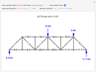
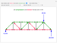
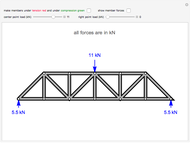
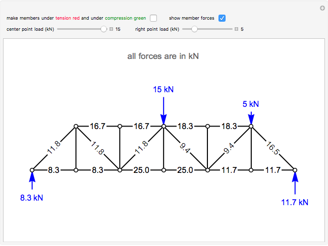
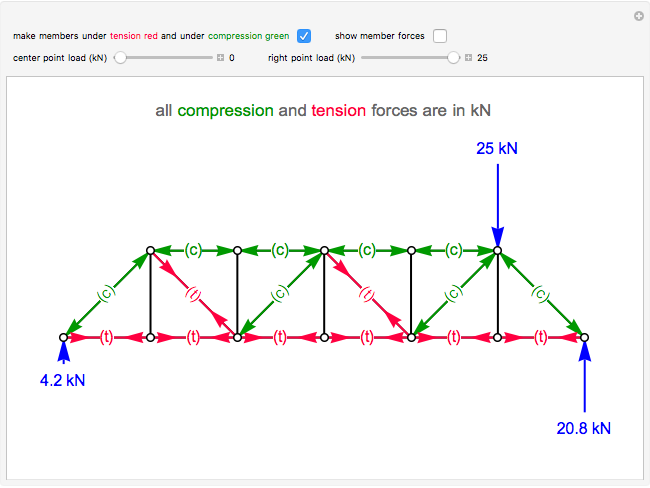
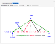
This Demonstration calculates the forces on the members of a planar truss.
[more]


Contributed by: Rachael L. Baumann (September 2017)
Additional contributions by: John L. Falconer
(University of Colorado Boulder, Department of Chemical and Biological Engineering)
Open content licensed under CC BY-NC-SA
Snapshots

Details
The method of joints is used to calculate the forces on each member of the truss. This is done by solving force balances around individual joints. First, calculate the reactions at the supports. Taking the sum of the moments at the left support:
 ,
,
where  is the moment around support
  (left support),
  is the width of one member,
  is the force applied to the joints at
  , and
, and  is the reaction at support
  (right). The first two terms (
 and
and  ) in the moment balance are positive because they would cause a clockwise rotation, and the third term (
 ) is negative because it would cause a counterclockwise rotation.
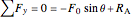
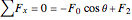
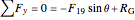
Next, take the sum of the forces in the  direction to get
  :
:
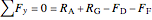 .
.
Begin solving for the forces of the members by doing force balances at the joints. The order of the balances around the joints listed here is the order in which they should be solved. Force balances are done assuming we can use logic to figure out which members are under tension and which are under compression. Starting at joint , there is a reaction force pushing up, so  must be pushing down (under compression). A labeled truss is shown in Figure 1.
Joint
 ,
,
 .
.
Joint 
 ,
,
 .
.
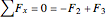
Joint 
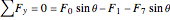 ,
,
 .
.
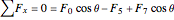
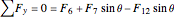
Joint 
 ,
,
 .
.
Joint 
 ,
,
 .
.
Joint 
 ,
,
 .
.
Joint 
 ,
,
 .
.
Joint 
 ,
,
 .
.
Joint 
 ,
,
 .
.
Joint 
 ,
,
 .
.
Joint
 .
.
Note that all the vertical members are zero members, which means they are neither under tension nor under compression (force is 0 kN).
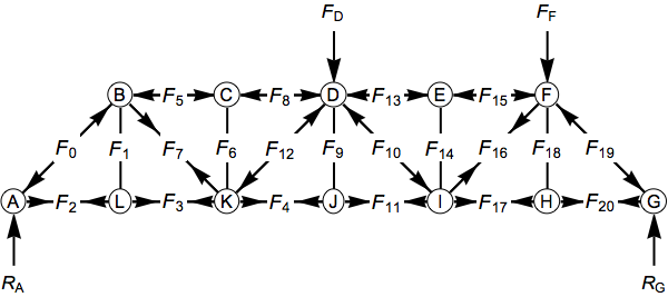
Figure 1.
Reference
[1] SkyCiv Cloud Engineering Software. "Tutorial to Solve Truss by Method of Sections." (Aug 29, 2017) skyciv.com/tutorials/tutorial-to-solve-truss-by-method-of-sections.
Permanent Citation
 Determine the Type of Stress in Each Member of a Truss
Rachael L. Baumann Determine if a Truss Can Be Solved
Rachael L. Baumann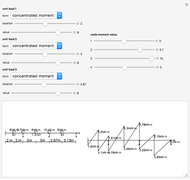 Internal Force Calculation for a Continuous Beam
Junlin Zhang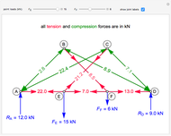 Solving a Double Scissor Truss
Rachael L. Baumann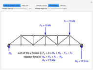 Method of Sections to Solve a Truss
Rachael L. Baumann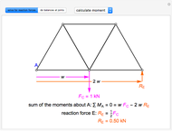 Method of Joints to Solve a Truss Problem
Rachael L. Baumann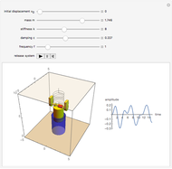 Forced Oscillations
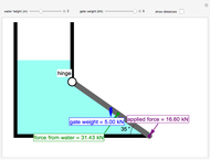
Stephen Wilkerson and Mark Evans (Towson University)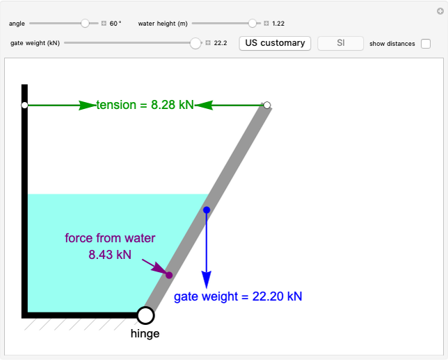 Forces on a Partially Submerged Gate
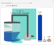
Rachael L. Baumann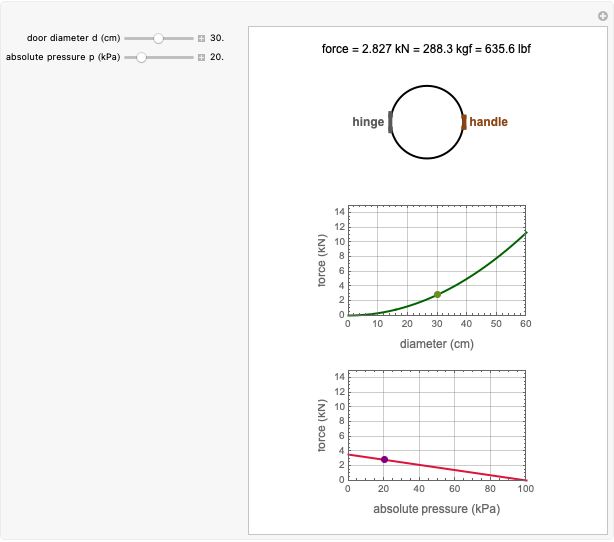 Force to Overcome Vacuum Pull
Mark D. Normand and Micha Peleg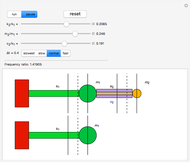 Tuned Mass Damper
Nabil Fares
-
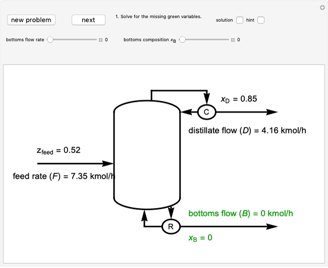
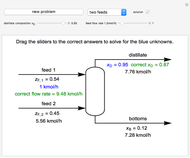 Solving Mass Balances on a Distillation Column
Rachael L. Baumann -
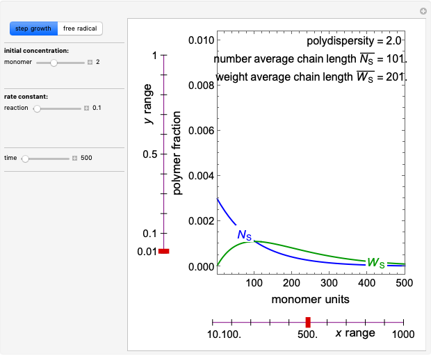 Polymerization in a Batch Reactor
Rachael L. Baumann -
 Construct a McCabe-Thiele Diagram for Distillation
Rachael L. Baumann -
 Construct an x-y Diagram for a Stripping Column
Rachael L. Baumann -
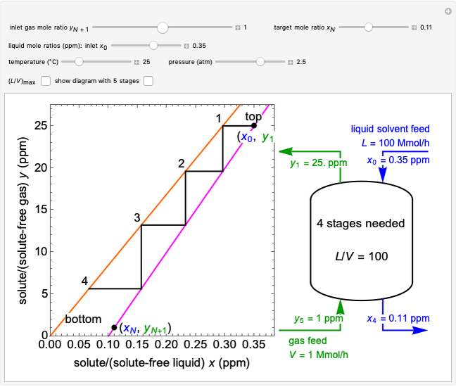
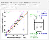
 Construct an x-y Diagram for an Absorption Column
Rachael L. Baumann -
 Construct a Conversion-Temperature Diagram for a Reversible Adiabatic Reaction
Rachael L. Baumann -
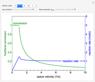 Reactor Rate and Conversion versus Space Velocity
Rachael L. Baumann -
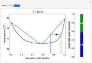
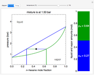
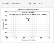 Construct a T-x-y Diagram for Vapor-Liquid Equilibrium (VLE)
Rachael L. Baumann -
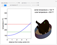 Cooking a Turkey
Rachael L. Baumann -
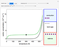 Electrical Conductivity of Silicon Semiconductors
Rachael L. Baumann -
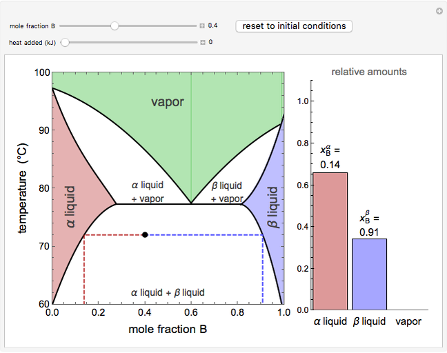 Vapor-Liquid-Liquid Equilibrium (VLLE)
Rachael L. Baumann -
 Vapor-Liquid Equilibrium Diagram for Non-Ideal Mixture
Rachael L. Baumann -
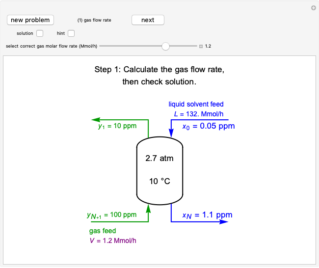
 Stripping Column Operation
Rachael L. Baumann -
 P-x-y and T-x-y Diagrams for Vapor-Liquid Equilibrium (VLE)
Rachael L. Baumann -
 Forces on a Completely Submerged Gate
Rachael L. Baumann -
 Evaporative Cooling of Water
Rachael L. Baumann -
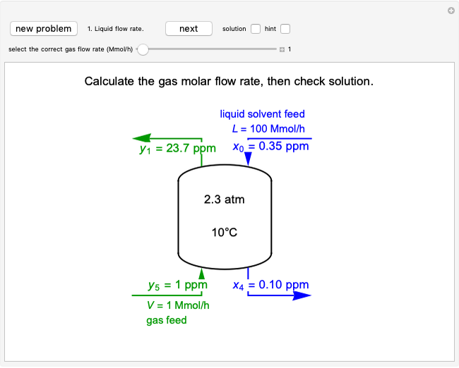
 Operation of an Absorption Column
Rachael L. Baumann -
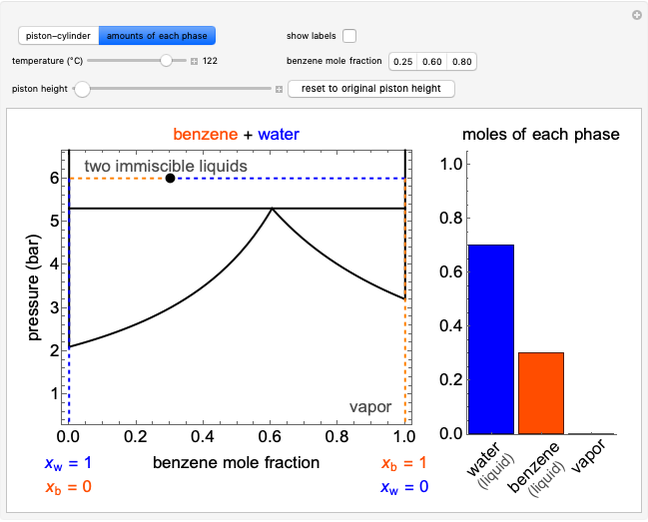 Immiscible Liquids on Pressure-Composition Diagram
Rachael L. Baumann -
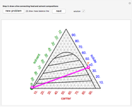
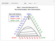 Apply the Hunter-Nash Method to Liquid-Liquid Extraction
Rachael L. Baumann -
 Construct Single-Stage, Liquid-Liquid Extraction
Rachael L. Baumann