Instrumental Polarization of a Beam Scanner


Requires a Wolfram Notebook System
Interact on desktop, mobile and cloud with the free Wolfram Player or other Wolfram Language products.
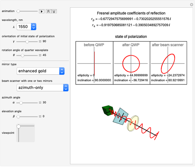
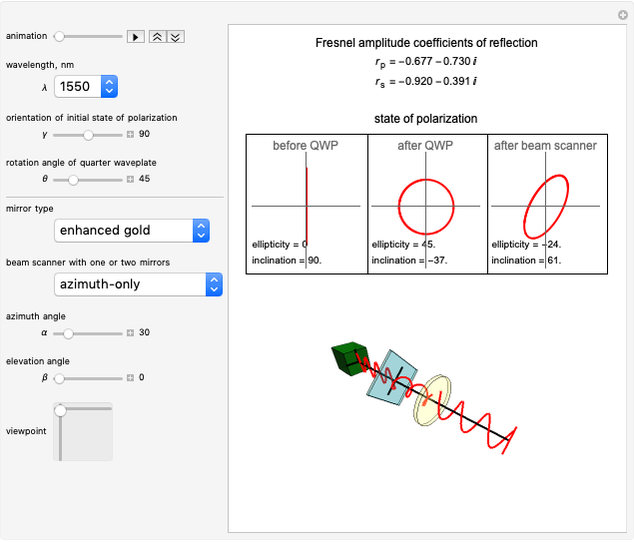
This Demonstration shows the induced changes in the state of polarization (SOP) of the incident beam upon reflection off mirrors in a beam scanner. The Fresnel coefficients are calculated along with the SOP for three common mirror coatings at three different wavelengths. You can vary the incident polarization and the orientation of the mirrors and observe the effect on the SOP in three dimensions in real time.
Contributed by: Sarah Knudsen, Tayari Coleman, Lauren Gorman and Anna Petrova-Mayor (June 2020)
Open content licensed under CC BY-NC-SA
Snapshots
Details
This Demonstration shows the induced state of polarization (SOP), known as instrumental polarization, upon reflection off mirrors of a beam scanner. The calculations are done using Jones calculus [1, 2]. The values at 1550nm were experimentally verified [2, 3].
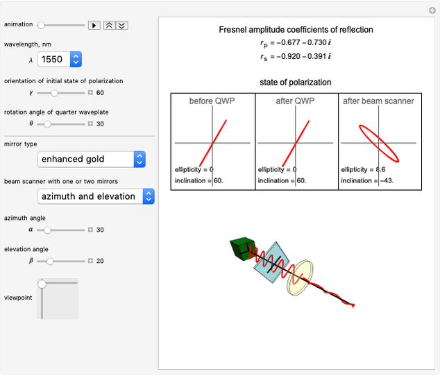
There are two setups for the beam scanner to choose from: "azimuth-only" and "elevation-over-azimuth". For the azimuth-only beam scanner, the incident beam travels parallel to the optical table, reflects off a launch mirror becoming vertical to the optics table, then reflects off the azimuthal mirror. By changing the azimuthal angle, the reflected beam scans in the horizontal plane. An azimuthal angle of 0° means that the beam transmitted through the scanner points in the same direction as the incident beam. An azimuthal angle of 90° sends the beam counterclockwise from the initial direction. For the elevation-over-azimuth scanner, there is an additional mirror after the azimuthal mirror, the elevation mirror. By rotating the elevation mirror, the beam scans in the vertical plane.
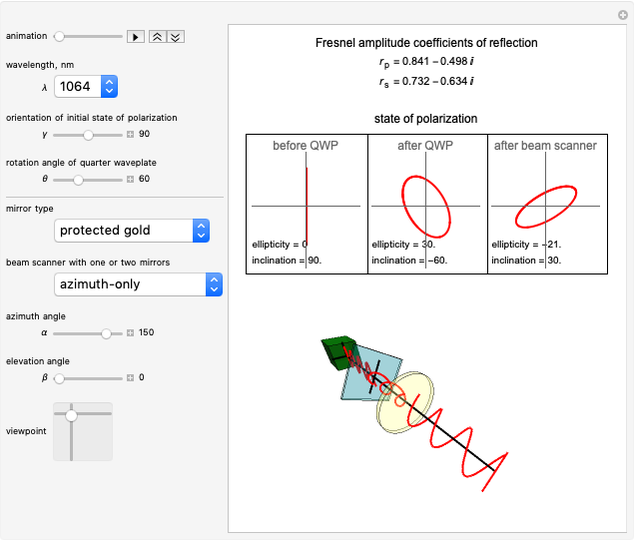
The components described in this Demonstration consist of the scanner, including the launch mirror, and three types of mirrors for the widely used wavelengths: 633nm, 1064nm and 1550nm. The mirrors are protected gold (PG), protected aluminum (PA) and enhanced gold (EG). Protected gold and protected aluminum are off the shelf from Thorlabs (PF10-03-M01 and PF10-03-G01, respectively), while the enhanced gold is a custom coating that contains four pairs of  and
and  [4–6].
You can select the incident SOP on the launch mirror by rotating the initially linearly polarized light, along with a quarter wave plate (QWP).
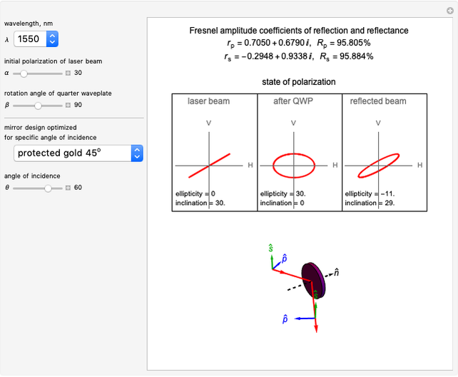
The top panel displays the Fresnel coefficients for the mirrors, the initial state of polarization, the polarization after the QWP and the polarization after the beam scanner. The polarization state is characterized in terms of ellipticity and inclination angle.
The dynamic 3D panel shows the SOP from the laser (green box), after the QWP (blue box) and after the set of launch mirror and beam scanner mirror (yellow cylinder).
The 3D dynamic panel was built using the source code from [7].
References
[1] E. Hecht, Optics, 5th ed., Boston: Pearson Education, Inc., 2017.
[2] A. Petrova-Mayor and S. Knudsen, "Analysis and Manipulation of the Induced Changes in the State of Polarization by Mirror Scanners," Applied Optics, 56(15), 2017 pp. 4513–4521. doi:10.1364/ao.56.004513.
[3] A. Petrova-Mayor and S. Gimbal, "Advanced Lab on Fresnel Equations," American Journal of Physics, 83(11), 2015 pp. 935–941. doi:10.1119/1.4929969.
[4] Thorlabs, Inc. www.thorlabs.com.
[5] S. D. Mayor, A. Petrova-Mayor, R. W. Wortley, D. S. Hofstadter, S. M. Spuler and J. Ranson, "Gas-Fusion Mirrors for Atmospheric Lidar," in Frontiers in Optics 2011/Laser Science XXVII, San Jose, CA, 2011, Washington, DC: Optical Society of America, 2011 paper JWA19. doi:10.1364/FIO.2011.JWA19.
[6] Angstrom Sun Technologies, Inc. www.angstec.com.
[7] F. E. Moolekamp and K. L. Stokes, "Polarization of an Optical Wave through Polarizers and Wave Plates" from the Wolfram Demonstrations Project—A Wolfram Web Resource. demonstrations.wolfram.com/PolarizationOfAnOpticalWaveThroughPolarizersAndWavePlates.
Permanent Citation
 Reflectivity and Induced Polarization by Mirrors
Tayari Coleman, Anna Petrova-Mayor and Sarah Knudsen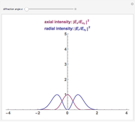 Radially Polarized Laser Beam Intensity Distributions
Yousef I. Salamin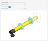 Light Beams through Multiple Polarizers
S. M. Blinder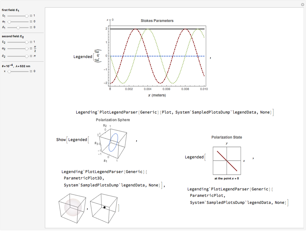 Stokes Parameters for Superposition of Two Slightly Noncollinear Polarized Beams
B. M. Rodríguez-Lara and I. Ricardez-Vargas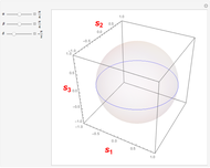 Stokes Parameters for the Superposition of Two Slightly Noncollinear Light Beams with Orthogonal Polarizations
B. M. Rodríguez-Lara and I. Ricardez-Vargas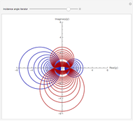 Polarization State Generator
Siva Perla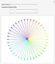 State of Light Polarization
Ertan Salik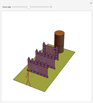 Understanding Polarization with an Analogy
Enrique Zeleny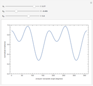 A Rotating Waveplate Polarization Analyzer
Beth Schaefer and Edward Collett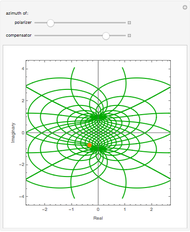 Polarizer-Compensator Combination as a Controlled Polarization Filter
Siva Perla