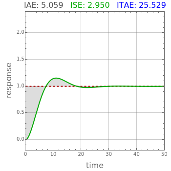
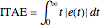
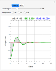
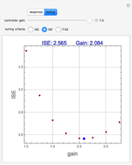
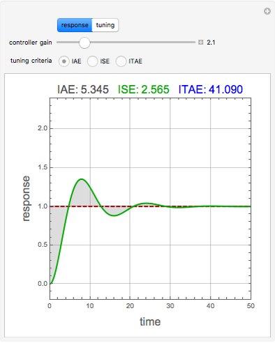
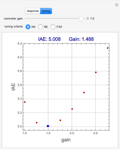
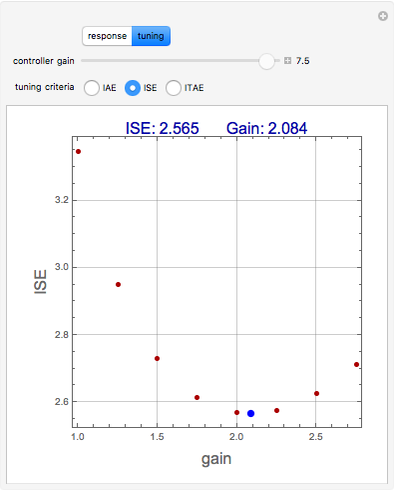
Integral Error Criteria for Controller Tuning
Initializing live version


Requires a Wolfram Notebook System
Interact on desktop, mobile and cloud with the free Wolfram Player or other Wolfram Language products.
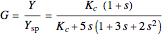
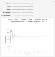
Consider the closed loop shown in Figure 10.8 in [1], where  ,
,  ,
,  ,
,  , and
, and  .
.


Contributed by: Housam Binous, Mohammad Mozahar Hossain, and Ahmed Bellagi (December 2015)
Open content licensed under CC BY-NC-SA
Snapshots

Details
Reference
[1] D. E. Seborg, T. F. Edgar, D. A. Mellichamp, and F. J. Doyle III, Process Dynamics and Control, 3rd ed., Hoboken, NJ: John Wiley & Sons, Inc., 2011.
Permanent Citation
Related Demonstrations
More by Author
 Proportional Temperature Control
Jeff Bryant Step Response with a P Controller
Doug Looze Simulation of Feedback Control System with Controller and Second-Order Plant
Nasser M. Abbasi Inverted Pendulum Controls
Stephen Wilkerson (Towson University) and Nathan Slegers (University of Alabama, Huntsville) with contributions by Franz Brandhuber First-Order Transfer Functions in Process Control
Simon M. Lane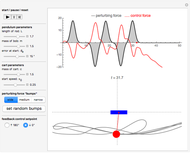 Automatic Feedback Control of a Pendulum-and-Cart System
Erik Mahieu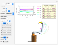 Joint Space and Tooling Space for Robot Motion Control
Frederick Wu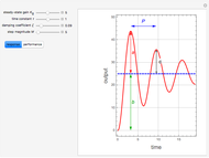 Performance Characteristics for Step Response of an Underdamped Process
Housam Binous, Mohammad Mozahar Hossain, and Ahmed Bellagi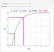 Sundaresan-Krishnaswamy Technique for Estimation of Process Parameters
Housam Binous, Mohammad Mozahar Hossain, and Ahmed Bellagi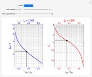 Smith's Second-Order Method in Process Dynamics
Housam Binous, Mohammad Mozahar Hossain, and Ahmed Bellagi
-
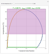 Liquid-Liquid Equilibrium for the 1-Butanol-Water System
Ahmed Bellagi -
 Temperature Dependence of Dehydrogenation of Ethyl Benzene to Styrene
Ahmed Bellagi -
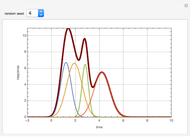 Deconvolution of a Chromatogram
Ahmed Bellagi -
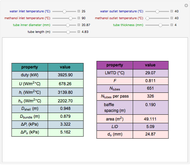 Design of a Shell and Tube Heat Exchanger
Ahmed Bellagi -
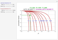 Correction Factor for Shell and Tube Heat Exchanger
Ahmed Bellagi -
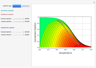 Contour Plots for Reaction Rates
Ahmed Bellagi -
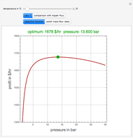 Optimal Conditions for CO2/n-Hexane Flash Separation
Ahmed Bellagi -
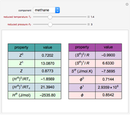
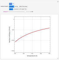 Residual Functions for the SRK and PR Equations of State
Ahmed Bellagi -
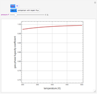 Gas-Phase Fugacity Coefficients for Propylene
Ahmed Bellagi -
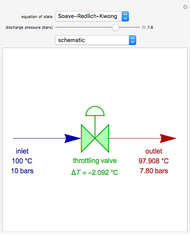 Operation of a Throttling Valve
Ahmed Bellagi -
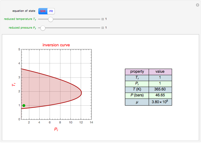 Joule-Thomson Inversion Curves for Soave-Redlich-Kwong (SRK) and Peng-Robinson (PR) Equations of State
Ahmed Bellagi -
 Lee-Kesler Generalized Correlations for Gases
Ahmed Bellagi -
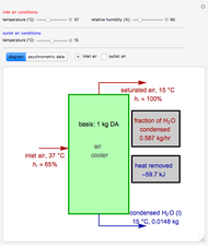 Operation of an Air Conditioner
Ahmed Bellagi -
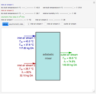 Adiabatic Mixing of Two Moist Air Streams
Ahmed Bellagi -
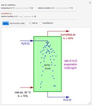 Adiabatic Humidification
Ahmed Bellagi -
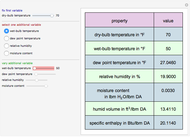 Psychrometric Data Calculator in English Engineering Units
Ahmed Bellagi -
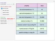 Psychrometric Data Calculator in SI Units
Ahmed Bellagi -
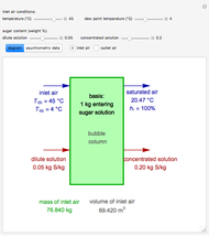 Concentration of Sugar Solution in a Bubble Column
Ahmed Bellagi -
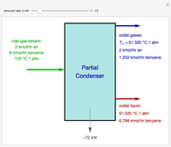 Operation of a Partial Condenser
Ahmed Bellagi -
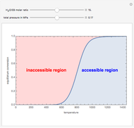
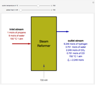 Steam Reforming of Propane
Ahmed Bellagi