Longitudinal Standing Waves

Requires a Wolfram Notebook System
Interact on desktop, mobile and cloud with the free Wolfram Player or other Wolfram Language products.
A sound wave in an organ pipe can be understood as the superposition of waves reflecting back and forth between the two ends, with destructive interference at nodes and constructive interference at antinodes.
[more]
Contributed by: Kenneth E. Caviness (August 2022)
Open content licensed under CC BY-NC-SA
Snapshots


Details
This Demonstration allows experimentation with standing waves in open and closed pipes, a commonly observed type of longitudinal wave motion [1]. Longitudinal waves (including sound waves, compression/expansion waves in a Slinky, and primary earthquake P waves) propagate through a solid, liquid or gas with a speed dependent on the density of the medium.
Wave reflection occurs at both closed and open pipe ends, with maximum displacement (motion) possible at an open end and minimum displacement possible at a closed end. Thus there is a displacement node at any closed end and an antinode at any open end.
This treatment makes a number of simplifications and ignores edge effects, assuming that there is a pressure node (and displacement antinode) at a pipe's open end and a pressure antinode (and displacement node) at a closed end. In a physical pipe, the position of the pressure node at the open end varies slightly, depending on the tube diameter. The left/right displacements and the arrows showing maximum displacements are also exaggerated for easier viewing and are not intended to show the actual motion of the air, only giving an idea of relative magnitudes of the drift velocities of the molecules at different positions in the pipe.
In an open pipe of length  , the only possible wavelengths forming standing waves are those such that
  is an integer multiple of the half-wavelength, while in a closed pipe,
  must be an odd integer multiple of the quarter-wavelength.
The main controls are the "harmonic n" buttons to select one of the allowed wavelengths to display, the "pipe end" buttons to specify that the right end of the pipe be "open" or "closed" ("none" means the pipe goes on forever and no reflected wave, no interference, no standing wave will occur) and the "time" controls to start/stop, speed up or slow down the animation.
The first three option buttons toggle the display of three waves: the standing wave itself and its rightward-moving and leftward-moving components. The next three buttons specify the visual representation: pressure contour lines (vertical lines whose spacings indicate differing pressures), density (scattered points that move in response to the wave motion and so give an indication of molecular displacements and air density) and transverse (included for comparison and easy identification of wave features). The next two buttons display wave envelopes and the last two add node/antinode labels.
A nice introductory exploration is to display an animated rightward-moving wave in various representations, add the leftward-moving reflection and then the standing wave, seeing how they interrelate. Add an "envelope"—showing the maximum displacement (left/right for longitudinal, up/down for the transverse visualization) and see how the air molecules alternately move left and right, clumping at displacement node positions (pressure antinode positions) whose labels can be toggled on/off.
Adjust the time controls to slow down the animation enough so it evolves smoothly, not jumping. The best speed will vary depending on the number of options simultaneously shown.
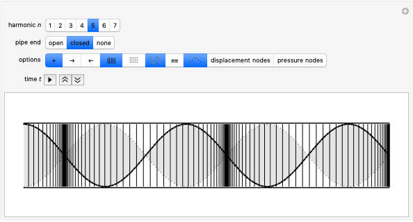
Snapshot 1: the rightward-moving component wave of the seventh harmonic in a closed pipe, shown as a sequence of pressure contour lines with the corresponding transverse wave; tight or wide spacing of the contour lines indicates high or low pressure regions, respectively
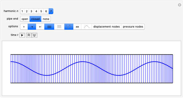
Snapshot 2: the same situation showing the composite standing wave and the transverse wave envelope as background: note the time-varying piling up of pressure contour lines at alternate displacement nodes, an indication that these are the antinodes of the pressure wave
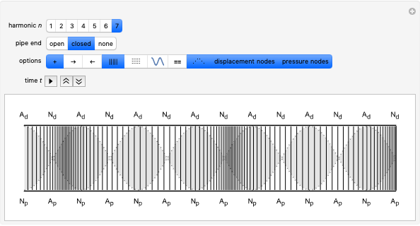
Snapshot 3: the same situation with air pressure and density visualized by a point distribution
Snapshot 4: the fundamental wavelength  for an open pipe, shown with high air pressure and density at the central pressure antinode (displacement node) and with the transverse wave envelope for comparison
Snapshot 5: comparison of the longitudinal and transverse envelopes for the fundamental mode  of an open pipe; note that the length of the pipe is filled with one-half wavelength
Snapshot 6: the fundamental wavelength  for a closed pipe, shown with high air pressure (closely spaced pressure contours) at the closed end (a displacement node) and with the transverse wave envelope for comparison; note that the length of the pipe is filled with one-quarter wavelength
The pipe length and wavelength relationships:
Open pipe: 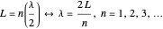
Closed pipe: 
For more information, see any college physics textbook, or see "Standing Wave" on Wikipedia.
Permanent Citation
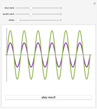 Superposition of Sound Waves
Alan Joyce Beat Frequency of Sound Waves
Christopher Engberg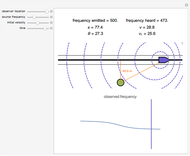 The Doppler Effect
Alan Joyce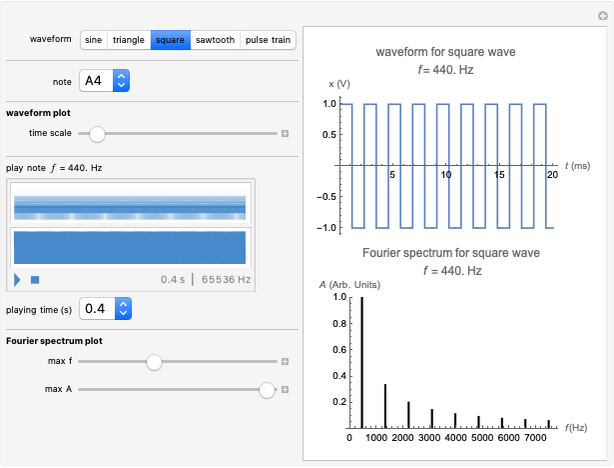 Sounds of Waveforms
Marilyn F. Bishop (Virginia Commonwealth University, Department of Physics and Center for the Study of Biological Complexity, Richmond, Virginia)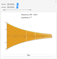 Sounds from Amplitude and Frequency
Paul Christiano (The Harker School) Transverse Standing Waves
Kenneth E. Caviness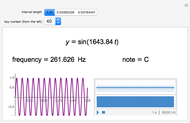 Sine Waves for Musical Scales
Eryn Stehr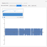 The Sound of Sine Waves
Abigail Nussey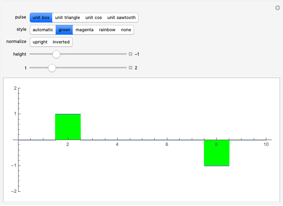 Superposition of Wave Pulses
Kenneth E. Caviness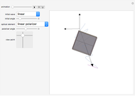 Polarization of an Optical Wave through Polarizers and Wave Plates
Fred E. Moolekamp and Kevin L. Stokes (University of New Orleans)
-
 Length Contraction Visualization: Pole and Barn
Kenneth E. Caviness -
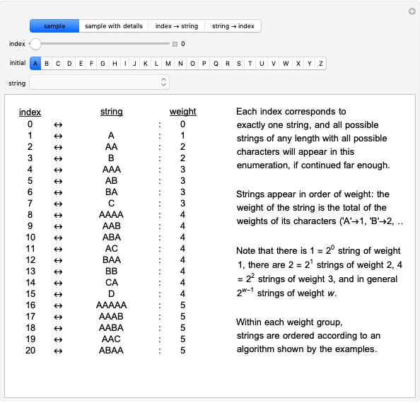 Universal String Enumeration
Kenneth E. Caviness -
 Longitudinal Standing Waves
Kenneth E. Caviness -
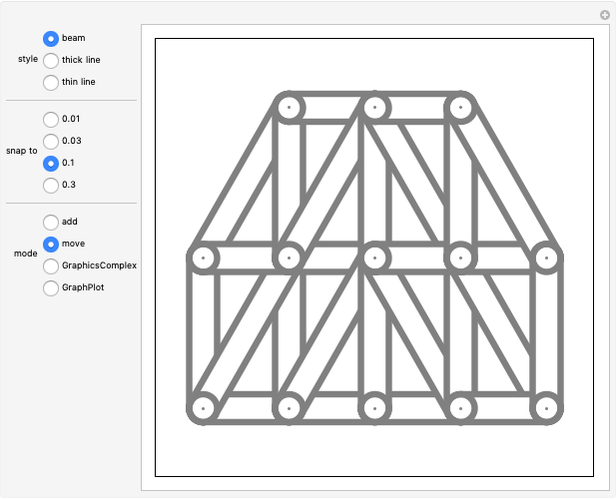 Two-Dimensional Truss Constructor
Kenneth E. Caviness -
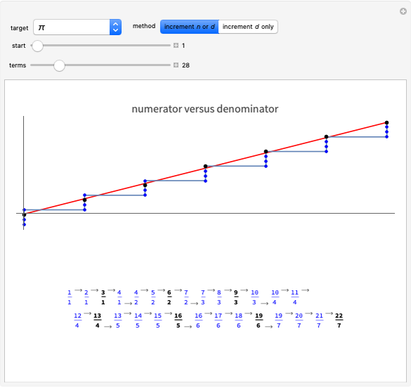 Finding Real-Number Approximants by Direct Methods
Kenneth E. Caviness -
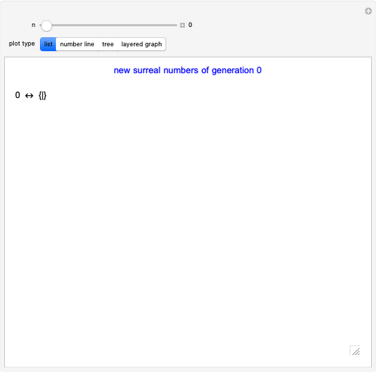 Generating the Surreal Numbers
Kenneth E. Caviness -
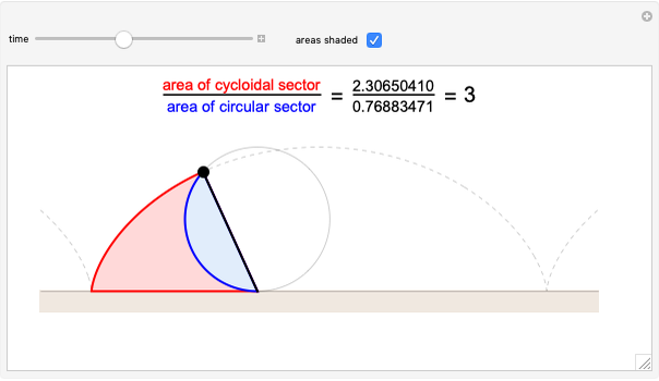 Cumulative Area under a Cycloid versus the Area of Its Rolling Circle
Kenneth E. Caviness -
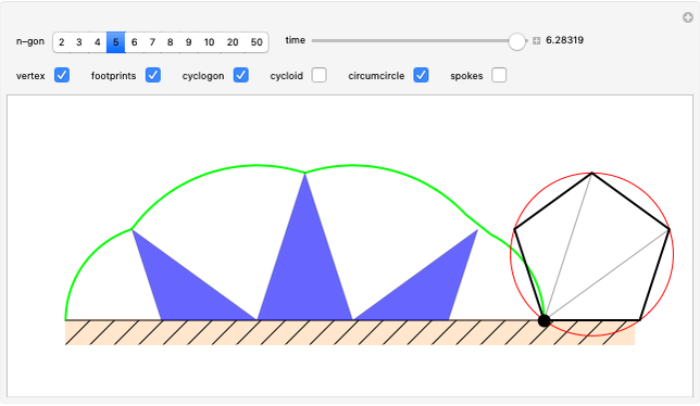 Cyclogons
Kenneth E. Caviness -
 Overlapping Light Colors
Kenneth E. Caviness -
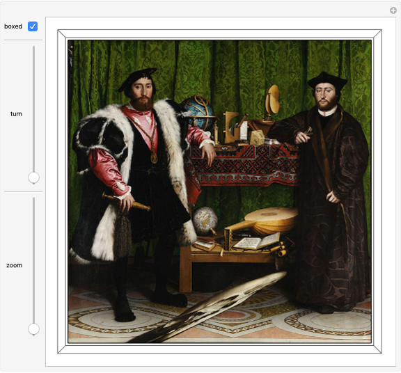 The Ambassadors, Interactive
Kenneth E. Caviness -
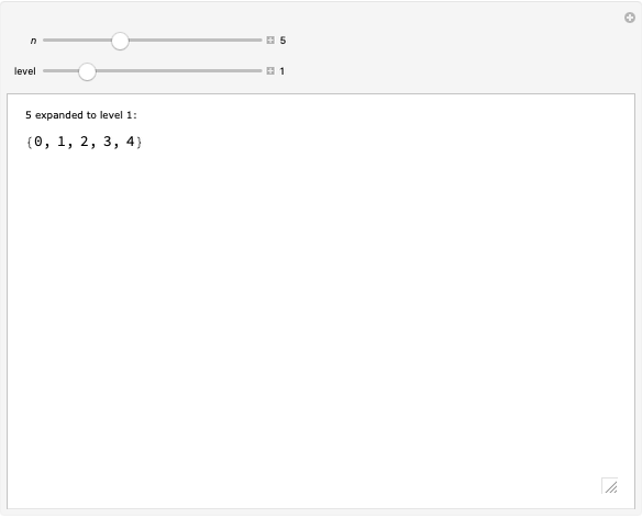 Numbers as Sets
Kenneth E. Caviness -
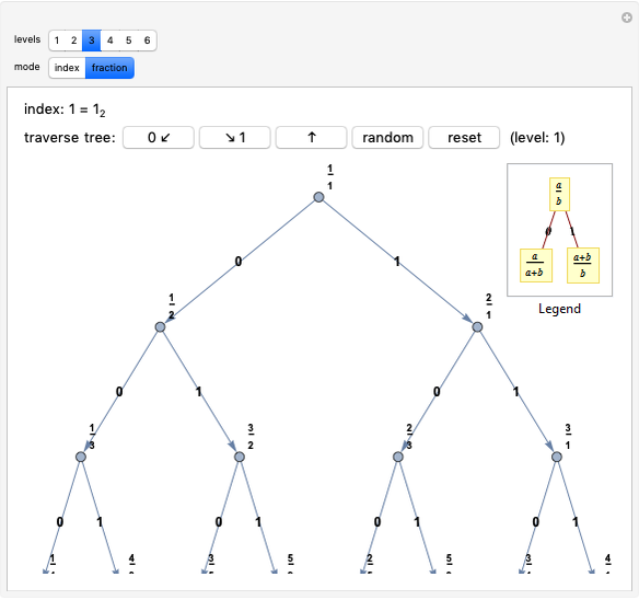 Calkin-Wilf Tree of Fractions
Kenneth E. Caviness -
 Electron Waves in Bohr Atom
Kenneth E. Caviness -
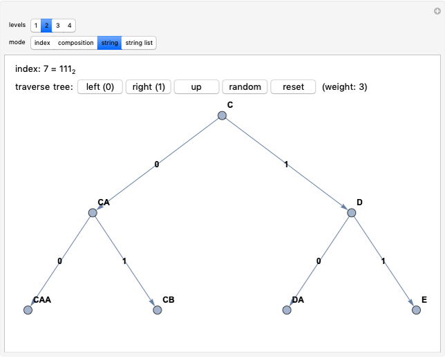 Tree of Strings
Kenneth E. Caviness -
Superposition of Wave Pulses
Kenneth E. Caviness -
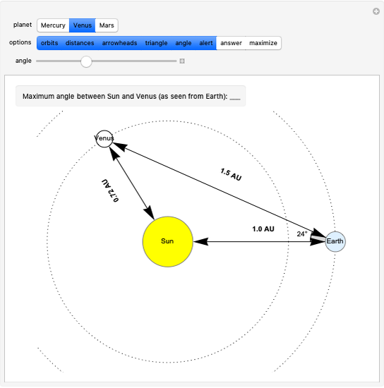 Greatest Planetary Elongation
Kenneth E. Caviness -
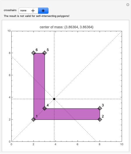 Center of Mass of a Polygon
Kenneth E. Caviness -
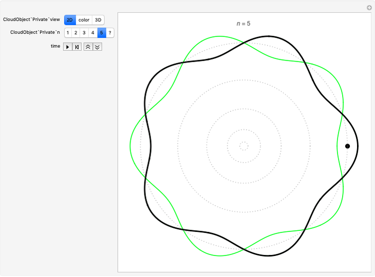
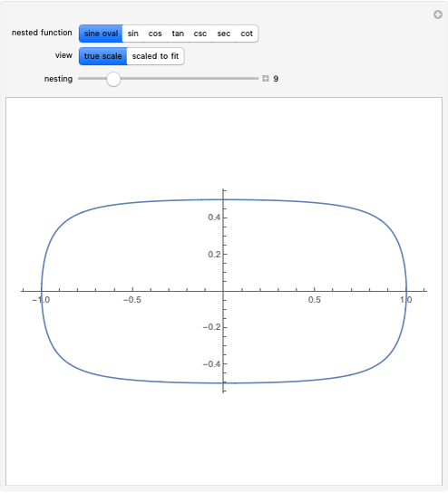 Sine Oval and Nested Trig Functions
Kenneth E. Caviness -
Transverse Standing Waves
Kenneth E. Caviness -
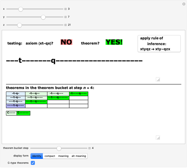 tq-System Explorer
Kenneth E. Caviness