Reflectivity and Induced Polarization by Mirrors

Requires a Wolfram Notebook System
Interact on desktop, mobile and cloud with the free Wolfram Player or other Wolfram Language products.
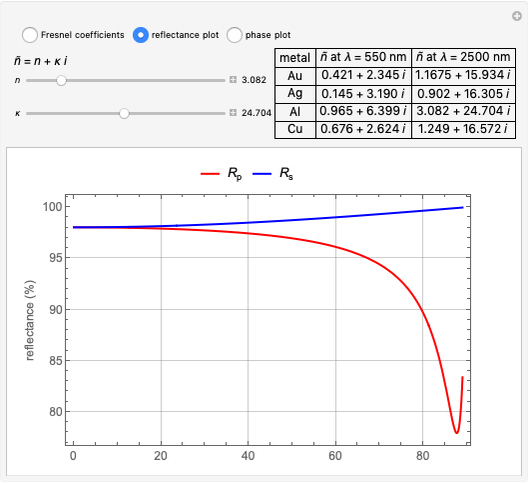
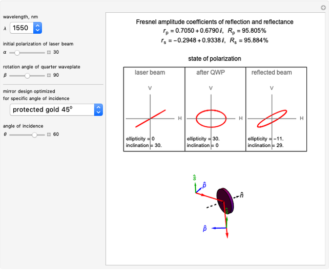
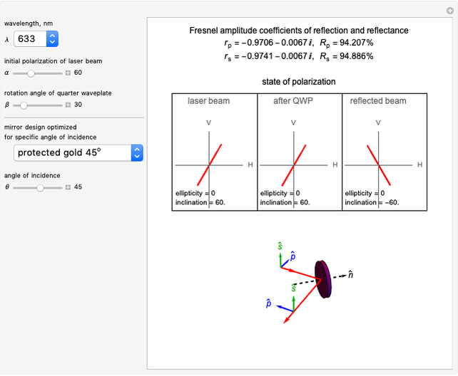
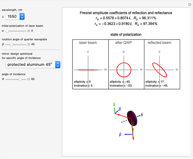
This Demonstration shows calculations of the induced state of polarization (SOP) upon reflection from a mirror (metallic or dielectric) and the reflectivity as a function of the angle of incidence (AOI). The calculations are done using Jones calculus [1, 2]. The results obtained with the metal-coated mirror at 1550 nm are experimentally verified with a polarimeter.
Contributed by: Tayari Coleman, Anna Petrova-Mayor and Sarah Knudsen (December 2020)
Open content licensed under CC BY-NC-SA
Snapshots

Details
Only  - and
- and  -linear polarizations are preserved upon reflection. Any other polarization state changes due to the difference in phase shifts of the
  and
and  components. The induced change depends on the wavelength of light, the type of mirror coating and the AOI. Hence, the mirror designs are optimized for maximum reflectivity at a given AOI (0 or 45 degrees).
You can select the wavelength (1550 nm or 633 nm) and define the incident polarization by rotating the initially linearly polarized light and a quarter-waveplate (QWP). You can choose from three mirrors. Two of them are off-the-shelf metal-coated mirrors from ThorLabs for AOI 45 degrees [3] (protected gold PF10-03-M01 and protected aluminum PF10-03-G01) and one is a typical quarter-wave dielectric stack for AOI 0. The design formula for the dielectric mirror is  , where
  stands for air,
  for high refractive index layer (ZnS here),
  for low refractive index (
 ),
),  for glass substrate (BK7), and 10 is the number of
  pairs. The thickness of the layers is calculated for the chosen wavelength as
  .
.
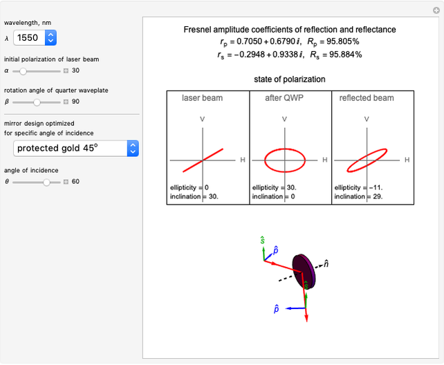
The top panel displays the Fresnel coefficients along with the reflectivity for  - and
- and  -polarization, the initial SOP of the laser beam, the polarization after the QWP (which is what is incident on the mirror) and the polarization of the reflected beam. The SOP is represented in the plane of the polarimeter (H-horizontal and V-vertical axes) and characterized in terms of ellipticity and inclination angle measured from the horizontal. The top panel was created after our Demonstration [4]. The bottom panel shows the mirror with the incident and reflected beams and the definitions of
  - and
- and  -polarizations. Here, the plane of incidence is horizontal and parallel to the optical table.
References
[1] E. Hecht, Optics, 5th ed., Boston: Pearson Education, Inc., 2017.
[2] A. Petrova-Mayor and S. Knudsen, "Analysis and Manipulation of the Induced Changes in the State of Polarization by Mirror Scanners," Applied Optics, 56(15), 2017 pp. 4513–4521. doi:10.1364/ao.56.004513.
[3] Thorlabs, Inc. www.thorlabs.com.
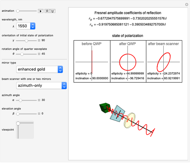
[4] S. Knudsen, T. Coleman, L. Gorman and A. Petrova-Mayor. "Instrumental Polarization of a Beam Scanner" from the Wolfram Demonstrations Project—A Wolfram Web Resource. demonstrations.wolfram.com/InstrumentalPolarizationOfABeamScanner.
Permanent Citation
 Instrumental Polarization of a Beam Scanner
Sarah Knudsen, Tayari Coleman, Lauren Gorman and Anna Petrova-Mayor Multiple Reflections in Two Mirrors
Jaime Rangel-Mondragon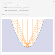 Reflection from a Polynomial Mirror
Stephen Wolfram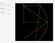 Reflection in a Parabolic Mirror
Izidor Hafner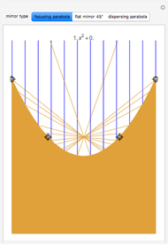 Reflection from a Freehand Polynomial Mirror
Machi Zawidzki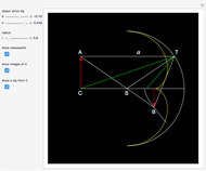 Reflecting inside a Spherical Mirror and a Catacaustic
Izidor Hafner Ray Diagrams for Spherical Mirrors
Ernest Lee Polarization State Generator
Siva Perla State of Light Polarization
Ertan Salik Understanding Polarization with an Analogy
Enrique Zeleny