AC Synchronous Machine Vector Diagram


Requires a Wolfram Notebook System
Interact on desktop, mobile and cloud with the free Wolfram Player or other Wolfram Language products.
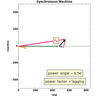
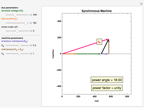
The principles of an AC synchronous machine are illustrated with dynamic vectors. This allows for an understanding of the interaction of various machine parameters.
Contributed by: Harley H. Hartman (March 2011)
Open content licensed under CC BY-NC-SA
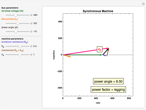
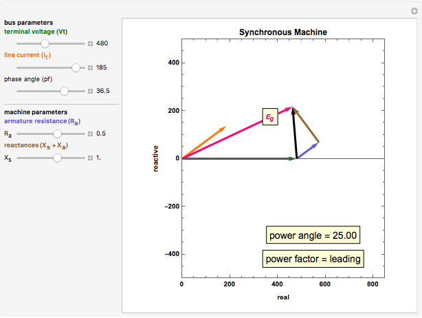
Snapshots


Details
You can adjust three bus parameters, terminal voltage, line current, and power factor. The power factor is adjustable, as it is the phase angle between the terminal voltage and the line current. You can also adjust two machine parameters, the armature resistance  ) and the sum of synchronous reactance, and armature reactance (
 +
+  ). These values are multiplied by the line current to create the appropriate voltage drops. The synchronous impedance voltage drop is then represented by the black vector. This is the vector sum of the voltage drops due to armature resistance, synchronous reactance, and armature reactance. You can observe the power angle variation as the angle between the terminal voltage (green) and the generated voltage
  ) changes.
Permanent Citation
"AC Synchronous Machine Vector Diagram"
http://demonstrations.wolfram.com/ACSynchronousMachineVectorDiagram/
Wolfram Demonstrations Project
Published: March 7 2011
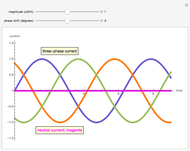 AC Three-Phase Neutral Current
Harley H. Hartman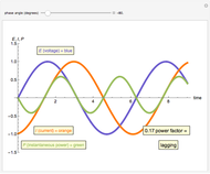 AC Power Factor Principle
Harley H. Hartman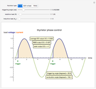 AC Thyristor Operation
Harley H. Hartman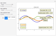 Simulating the Power Factor of an AC System
Harley H. Hartman AC Thyristor Trigger Angle versus Power Factor
Harley H. Hartman AC Induction Motor Rotor Design
Harley H. Hartman AC Rotating Magnetic Field Principle
Harley H. Hartman Operating an AC Three-Phase Induction Motor
Harley H. Hartman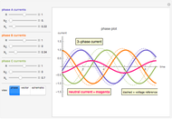 Simulating the Neutral Current of an AC System
Harley H. Hartman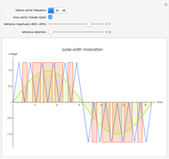 Pulse Width Modulation Principle
Harley H. Hartman
-
AC Thyristor Trigger Angle versus Power Factor
Harley H. Hartman -
Operating an AC Three-Phase Induction Motor
Harley H. Hartman -
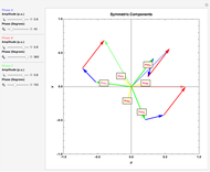 Fortescue's Theorem for a Three-Phase Unbalanced System
Harley H. Hartman -
AC Rotating Magnetic Field Principle
Harley H. Hartman -
Simulating the Power Factor of an AC System
Harley H. Hartman -
Simulating the Neutral Current of an AC System
Harley H. Hartman -
AC Power Factor Principle
Harley H. Hartman -
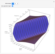 AC Induction Motor VFD Operation
Harley H. Hartman -
Pulse Width Modulation Principle
Harley H. Hartman -
AC Thyristor Operation
Harley H. Hartman -
AC Three-Phase Neutral Current
Harley H. Hartman -
AC Induction Motor Rotor Design
Harley H. Hartman -
 AC Synchronous Machine Vector Diagram
Harley H. Hartman