AC Transformers


Requires a Wolfram Notebook System
Interact on desktop, mobile and cloud with the free Wolfram Player or other Wolfram Language products.
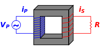
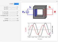
An electrical transformer is a device to change the voltage and amperage of alternating currents. In the simple design shown here,  primary wire coils (blue) and
  secondary coils (red) are wound around a ferromagnetic core. An alternating current in the primary circuit creates a time-dependent magnetic field in the core, which, in turn, induces an alternating current in the secondary circuit, via Faraday's law of electromagnetic induction. The respective rms voltages are in the same ratio as the numbers of turns:
  . If
. If  , this acts as a step-down transformer. Long-distance transmission lines use high voltage and low currents to minimize energy losses. A sequence of step-down transformers then reduces the voltage to household levels (120 volts in the U.S.). If the secondary resistance and induction are negligibly small (simplified model), the primary and secondary currents are given by the reciprocal relation
  .
.


Contributed by: S. M. Blinder (September 2008)
Open content licensed under CC BY-NC-SA
Snapshots


Details
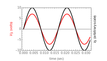
Snapshot 1: step-down transformer reducing the rms voltage from 120 to 30 volts
Snapshot 2: step-up transformer increasing the rms voltage from 120 to 240 volts
Snapshot 3: transformer with load in circuit; secondary voltage and current are now out of phase
Permanent Citation
 Improving Power Factors in an AC Circuit
Anping Zeng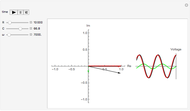 Phasor Model for RC Filter Electronic Circuit
Michael R. Braunstein (Central Washington University) Galvanometer as a DC Multimeter
S. M. Blinder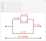 Effective Resistance of Network
S. M. Blinder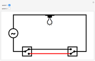 Three-Way Switches
S. M. Blinder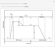 Potential Differences in a Circuit with an EMF Source
Enrique Zeleny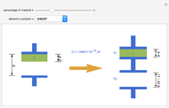 Partially Filled Capacitor
Enrique Zeleny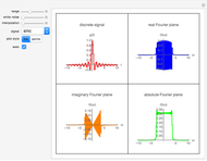 Complex and Real Planes of Discrete Fourier Transforms
Daniel de Souza Carvalho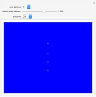 Directivity Pattern of Line Arrays
Christopher Purcell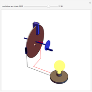 Faraday Disk Dynamo
S. M. Blinder
-
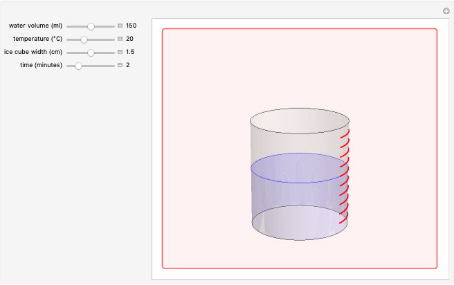 Ice Cube Melting in Water
S. M. Blinder -
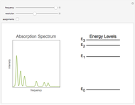 Absorption Spectroscopy
S. M. Blinder -
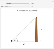 Height of Object from Angle of Elevation Using Tangent
S. M. Blinder -
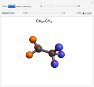 Internal Rotation in Ethane and Substituted Analogs
S. M. Blinder -
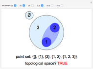 Topological Spaces on Three Points
S. M. Blinder -
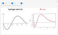 Hydrogen Atom in Curved Space
S. M. Blinder -
 Multipurpose Tool
S. M. Blinder -
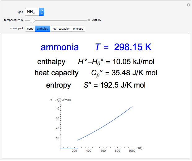 Statistical Thermodynamics of Ideal Gases
S. M. Blinder -
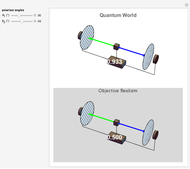 Bell's Theorem
S. M. Blinder -
 Kepler's Mysterium Cosmographicum
S. M. Blinder -
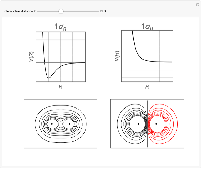 Bonding and Antibonding Molecular Orbitals
S. M. Blinder -
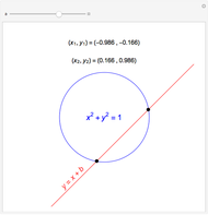 Visible and Invisible Intersections in the Cartesian Plane
S. M. Blinder -
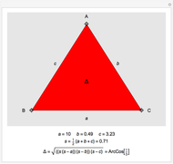 Heron's Formula
S. M. Blinder -
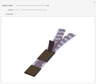 How Zippers Work
S. M. Blinder -
 Mittag-Leffler Expansions of Meromorphic Functions
S. M. Blinder -
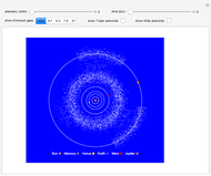 Orbital Resonance in the Asteroid Belt
S. M. Blinder -
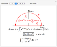 Jordan's Lemma Applied to the Evaluation of Some Infinite Integrals
S. M. Blinder -
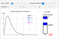 Configuration Interaction for the Helium Isoelectronic Series
S. M. Blinder -
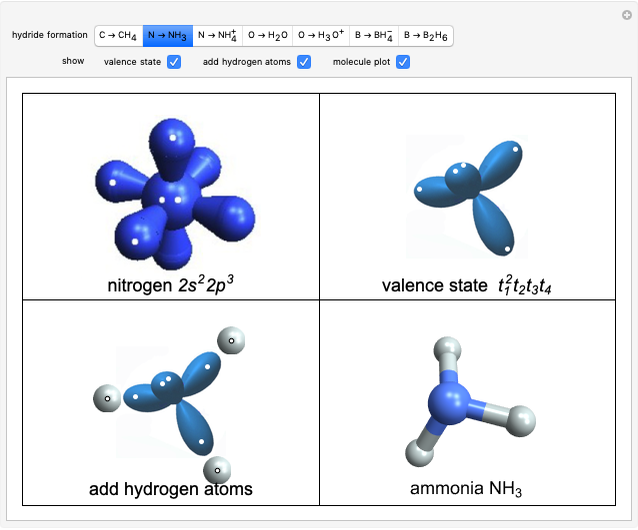 Structure and Bonding of Second-Row Hydrides
S. M. Blinder -
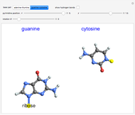 DNA Base Pairing
S. M. Blinder