Applying Mohr's Circles to Stress States of Continuum


Requires a Wolfram Notebook System
Interact on desktop, mobile and cloud with the free Wolfram Player or other Wolfram Language products.
A Mohr's circle is the representation of the stress state at any point of a continuum in a  -
- plane, where
  is the normal component of the stress vector on a given material facet and
  is its tangential component.
Contributed by: Maurizio Brocato (February 2020)
Open content licensed under CC BY-NC-SA
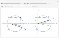
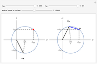
Snapshots


Details
Assume that we know the stress on the facet orthogonal to the  direction of the material space and that its scalar components are
  and
and  .
.
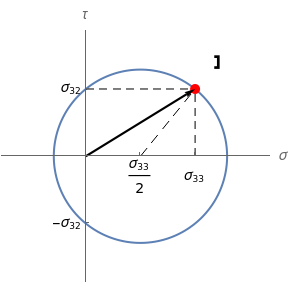
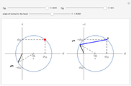
The direct method consists of drawing a circle centered at  and passing through the point
  in the
  -
- plane. When the normal to the facet rotates counterclockwise at an angle of
  , the stress vector on that facet is obtained by joining the origin to the point on the circle at a
  clockwise arc distance from
  .
.
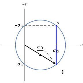
The so-called pole method is carried out by turning the  axis in the opposite direction (so that the direct frame is now
  -
- ) and drawing the circle centered at
  that passes through the point
  . This circle is thus visually the same figure as the previous one, but its points belong to a different plane. The point
  is named the pole of the Mohr's circle. When the normal to the facet rotates counterclockwise at an angle of
  , the stress vector on that facet is obtained by joining the origin to the point on the circle identified by the cord passing through the pole
  and parallel to the plane of the facet (i.e., rotated by the same angle
  and in the same direction from the
  axis).
The black arrow represents the stress vector. A symbolic representation of the material facet on which this vector acts is shown close to the stress vector head outside the circle. The construction on the right-hand side is the direct Mohr's circle; the one on the left-hand side is the pole-method circle. The blue segment (parallel to the facet) is the cord identifying the stress vector in the pole method.
More information about the example can be found in [1].
Reference
[1] M. Brocato, Cours de mécanique des structures. Volume 1. Poutres élastiques, Paris: Presses des Ponts, forthcoming.
Permanent Citation
 Mohr's Arbelos and Lamé's Ellipsoids
Maurizio Brocato Mohr's Circle and Failure Criterion for Planar Stress States
Felipe R. Amador V. Mohr's Circle and Stress Transformations
Nick Bongiardina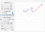 Principal Stresses and Mohr's Circle for Plane Stress
Nasser M. Abbasi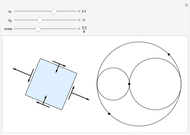 Planar Stress Rotation
Samuel Garcia Diethelm Principal Stresses in Compacted Cohesive Powders
Mark D. Normand and Micha Peleg Stress-Strain Analysis by the Finite Element Method
Yuncong Ma Crack Propagation and Stress Field for 2D Tensile Loads
Sam Shames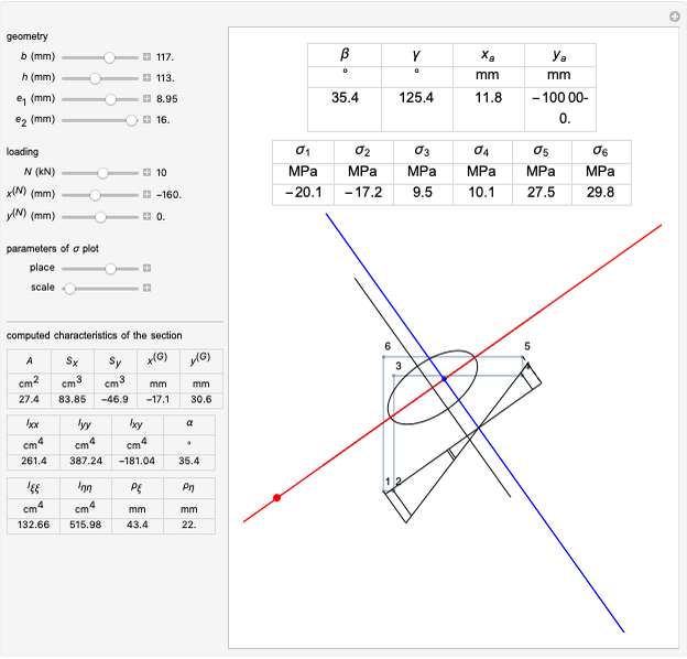 Bending and Stretching of an Elastic L-Beam
Maurizio Brocato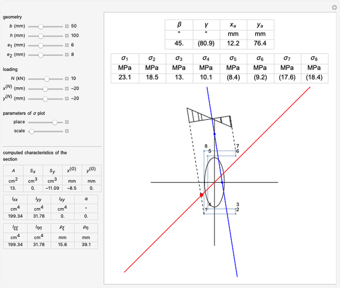 Bending and Stretching of an Elastic U-Beam
Maurizio Brocato