Electromagnetic Wave Incident on a Dielectric Boundary


Requires a Wolfram Notebook System
Interact on desktop, mobile and cloud with the free Wolfram Player or other Wolfram Language products.
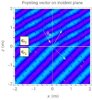
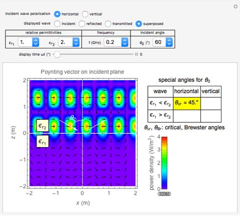
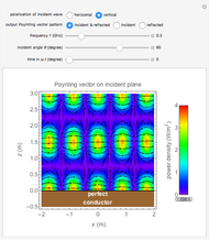
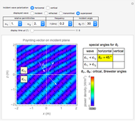
This Demonstration shows an electromagnetic wave incident on a planar dielectric boundary in terms of the Poynting vector on both sides of the boundary. Taking the incident plane and boundary planes to be  and
and  , respectively, the resulting Poynting vector pattern is shown on the incident
  -
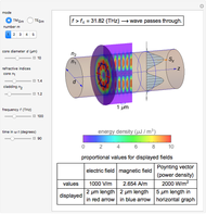
- plane. The incident wave is assumed to be linearly polarized either horizontally or vertically with respect to the electric field. (The horizontal wave and vertical wave are sometimes called the p-wave and s-wave, respectively.) In all the cases, the power density (Poynting vector intensity) of the incident wave is set to
  on average, that is, to peak at
 .
.


Contributed by: Y. Shibuya (October 2013)
Open content licensed under CC BY-NC-SA
Snapshots


Details
Snapshot 1: horizontally polarized incident wave with 
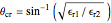
Snapshot 2: horizontally polarized incident wave with  ; the case of total reflection
Snapshot 3: vertically polarized incident wave with  ; the case of no reflection
According to Fresnel's equations for the horizontally polarized incident wave's electric field  , transmitted and reflected fields are expressed by
 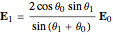 and
and 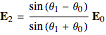 . Similar calculations can be made for the vertically polarized incident wave.
Generally, the upper half-space accommodates two waves: incident and reflected; therefore, the Poynting vector pattern is made up of undulating patterns. On the other hand, the lower half accommodates the transmitted wave only, showing a straight plane wave, provided . In the special case of Snapshot 3, the upper space shows the pattern of one plane wave, since there is no reflected wave.
Reference
[1] J. A. Stratton, Electromagnetic Theory, New York: McGraw-Hill, 1941 pp. 483–600.
Permanent Citation
 Electromagnetic Wave Incident on a Perfect Conductor
Y. Shibuya Electromagnetic Waves in a Cylindrical Waveguide
Y. Shibuya Electromagnetic Waves in a Parallel-Plate Waveguide
Y. Shibuya Electromagnetic Wave from Dipole over a Perfect Conductor
Y. Shibuya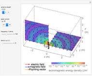 Electromagnetic Waves from a Linear Antenna
Y. Shibuya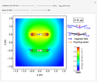 Electromagnetic Fields in Wireless Power Transmission
Y. Shibuya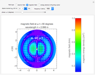 Electromagnetic Fields For Hertzian Dipoles
Y. Shibuya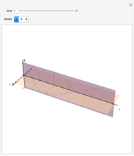 Electromagnetic Wave
Enrique Zeleny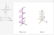 Polarization of an Electromagnetic Wave
Luis Jonathan Cervantes Rosas Variable States of Polarization Incident on a Wave Plate
Randall J. Hinton (Temple University)
-
 Skin Effects in Straight Wires
Y. Shibuya -
 Leakage Inductance in a Transformer
Y. Shibuya -
 Electromagnetic Wave Scattering by Conducting Sphere
Y. Shibuya -
 Cylindrical Cavity Resonator
Y. Shibuya -
 Electric Fields for Pairs of Cylinders or Spheres
Y. Shibuya -
Electromagnetic Fields in Wireless Power Transmission
Y. Shibuya -
 Wireless Power Transmission
Y. Shibuya -
 Surge Propagation in a Transmission Line
Y. Shibuya -
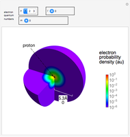 Electron Probability Distribution for the Hydrogen Atom
Y. Shibuya -
 Magnetic Shielding Effect of a Spherical Shell
Y. Shibuya -
Electromagnetic Waves from a Linear Antenna
Y. Shibuya -
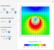 Current-Carrying Wire in Uniform Magnetic Field
Y. Shibuya -
 Electromagnetic Wave Incident on a Dielectric Boundary
Y. Shibuya -
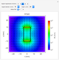 Magnetic Field and Magnetic Induction in a Cylindrical Bar Magnet
Y. Shibuya -
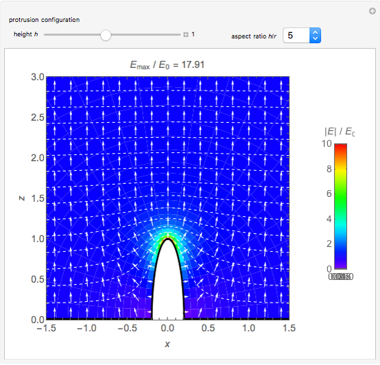 Spheroidal Protrusion in a Uniform Electric Field
Y. Shibuya -
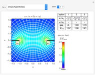 Electrostatic Fields Using Conformal Mapping
Y. Shibuya -
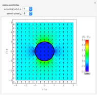 Dielectric Sphere in a Uniform Electric Field
Y. Shibuya -
 Electromagnetic Waves in Optical Fibers
Y. Shibuya -
Electromagnetic Waves in a Cylindrical Waveguide
Y. Shibuya -
Electromagnetic Waves in a Parallel-Plate Waveguide
Y. Shibuya