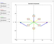
Fortescue's Theorem for a Three-Phase Unbalanced System


Requires a Wolfram Notebook System
Interact on desktop, mobile and cloud with the free Wolfram Player or other Wolfram Language products.
In 1918, C. L. Fortescue stated his theorem:  unbalanced phasors can be represented by systems of balanced phasors. Sequence components were created to facilitate calculations in unbalanced circuits and systems. Using the theory of symmetrical components, it is easier to analyze the problems of unbalanced systems (e.g. unbalanced load) and cases of faults in electric power systems (e.g. monophasic faults).
According to [1], "Fortescue defined a linear transformation from three-phase components to a new set of components called symmetrical components. The advantage of this transformation is that for balanced three-phase networks the equivalent circuit obtained for the symmetrical components, called sequence networks, are separated into three uncoupled networks. Furthermore, for unbalanced three-phase systems, the three sequence networks are connected only at the points of unbalance. As a result, sequence networks for many cases of unbalanced three-phase systems are relatively easy to analyze. The symmetrical component method is basically a modeling technique that permits systematic analysis and design of three-phase systems. Decoupling a detailed three-phase network into three simpler sequence networks reveals complicated phenomena in more simplistic terms. Sequence network results can then be superimposed to obtain three-phase results. The application of symmetrical components to unsymmetrical fault studies is indispensable."
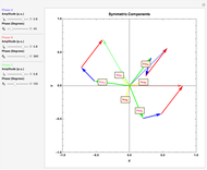
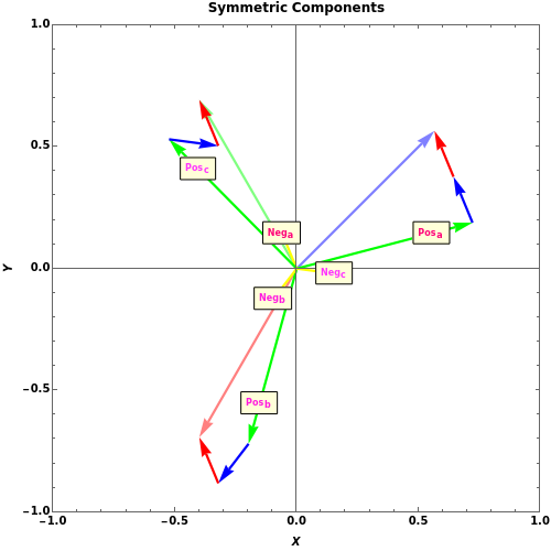
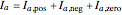
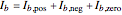
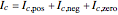
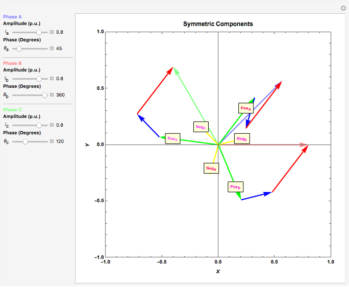
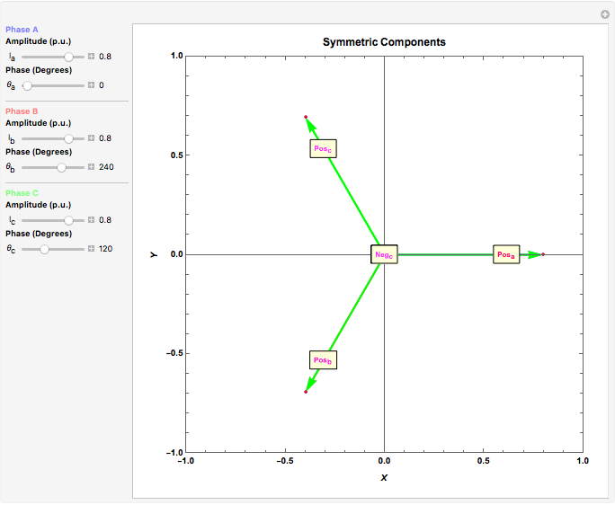
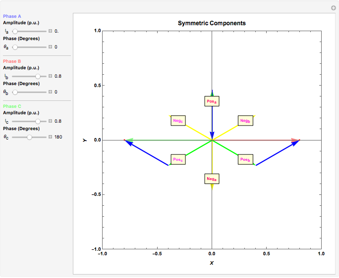
The positive sequence consists of three phasors, one for each phase, with
unbalanced phasors can be represented by systems of balanced phasors. Sequence components were created to facilitate calculations in unbalanced circuits and systems. Using the theory of symmetrical components, it is easier to analyze the problems of unbalanced systems (e.g. unbalanced load) and cases of faults in electric power systems (e.g. monophasic faults).
According to [1], "Fortescue defined a linear transformation from three-phase components to a new set of components called symmetrical components. The advantage of this transformation is that for balanced three-phase networks the equivalent circuit obtained for the symmetrical components, called sequence networks, are separated into three uncoupled networks. Furthermore, for unbalanced three-phase systems, the three sequence networks are connected only at the points of unbalance. As a result, sequence networks for many cases of unbalanced three-phase systems are relatively easy to analyze. The symmetrical component method is basically a modeling technique that permits systematic analysis and design of three-phase systems. Decoupling a detailed three-phase network into three simpler sequence networks reveals complicated phenomena in more simplistic terms. Sequence network results can then be superimposed to obtain three-phase results. The application of symmetrical components to unsymmetrical fault studies is indispensable."
The positive sequence consists of three phasors, one for each phase, with  degrees of angular displacement and equal magnitude. Thus, phase B is degrees from phase A, and phase C is degrees from phase B. A negative sequence is similar to the positive component, but instead of degrees, the displacement is
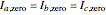
  degrees. The zero sequence is represented by three vectors of equal magnitude and equal angular displacement.


Contributed by: Daniel Motter (August 2011)
Based on a program by: Harley H. Hartman
Open content licensed under CC BY-NC-SA
Snapshots


Details
References
[1] http://users.ece.utexas.edu/~grady/_05_EE394J _ 2_Spring12 _Symmetrical _Components.pdf
[2] W. D. Stevenson, Jr., Elements of Power System Analysis, 3rd ed., New York: McGraw–Hill, New York, 1975.
[3] http://csus-dspace.calstate.edu/bitstream/handle/10211.9/1369/PDF.pdf?sequence=1
[4] http://en.wikipedia.org/wiki/Symmetrical_components
[5] http://www.elect.mrt.ac.lk/EE423_%20 Fault_Analysis _Notes.pdf
[6] http://www.gedigitalenergy.com/smartgrid/Dec07/7-symmetrical.pdf
Permanent Citation
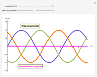 AC Three-Phase Neutral Current
Harley H. Hartman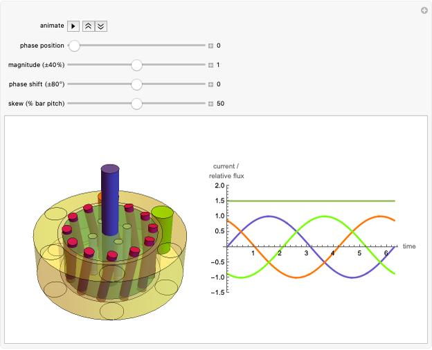 Operating an AC Three-Phase Induction Motor
Harley H. Hartman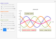 Simulating the Neutral Current of an AC System
Harley H. Hartman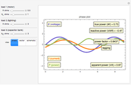 Simulating the Power Factor of an AC System
Harley H. Hartman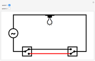 Three-Way Switches
S. M. Blinder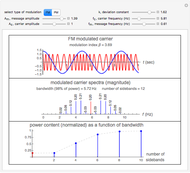 Power Content of Frequency Modulation and Phase Modulation
Nasser M. Abbasi AC Rotating Magnetic Field Principle
Harley H. Hartman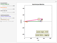 AC Synchronous Machine Vector Diagram
Harley H. Hartman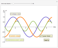 AC Power Factor Principle
Harley H. Hartman AC Thyristor Trigger Angle versus Power Factor
Harley H. Hartman