Heat Transfer in a Heat Exchanger


Requires a Wolfram Notebook System
Interact on desktop, mobile and cloud with the free Wolfram Player or other Wolfram Language products.
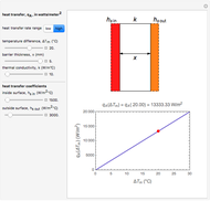
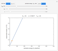
This Demonstration calculates and plots the heat flow,  (in watts/
 ), through a heat exchanger's wall of a chosen thickness,
  (in mm), and thermal conductivity,
  (in watts/m °C), with chosen surface heat transfer coefficients at either side of the wall,
  and
and  (in watts/
 °C), and logarithmic mean temperature difference, Δ
 (in °C), between them. Since the heat transfer coefficients can vary over a very large range, the
  and
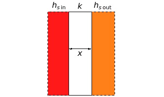
and  parameters can be specified as being high or low using a setter bar. The calculations are done using the equation
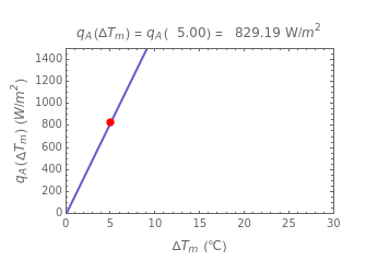
  , whose parameters can be modified by moving sliders. The red dot on the plot marks the heat flow per unit area for a Δ
 chosen by moving the top slider. The top graphic depicts the heat resistances as a schematic diagram (not to scale).
Contributed by: Mark D. Normand, Maria G. Corradini, and Micha Peleg (March 2011)
Open content licensed under CC BY-NC-SA
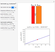
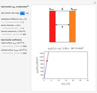
Snapshots

Details
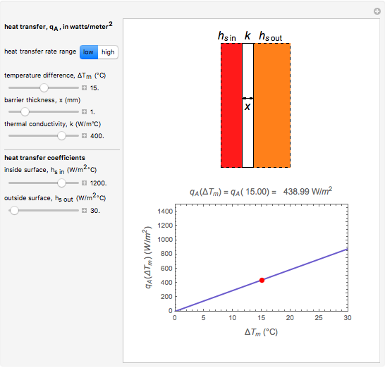
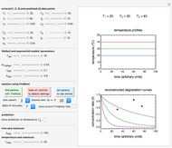
Snapshot 1: heat transfer through a thin, good conducting wall with flowing liquid on the inside and moving air on the outside
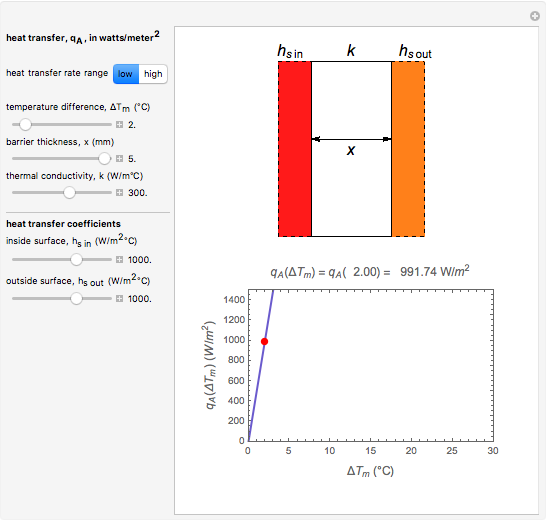
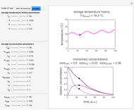
Snapshot 2: heat transfer through a thick, good conducting wall with flowing liquids on both sides
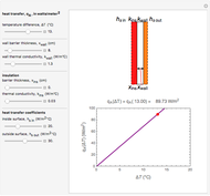
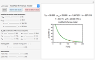
Snapshot 3: heat transfer through a thick, poorly conducting wall with flowing liquids on both sides
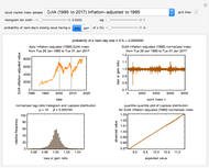
Snapshot 4: heat transfer through a thick, poorly conducting wall with condensing liquids on both sides
Reference: R. L. Earle with M. D. Earle, Unit Operations in Food Processing, NZIFST, Inc., 1983. (http://www.nzifst.org.nz/unitoperations/)
Permanent Citation
"Heat Transfer in a Heat Exchanger"
http://demonstrations.wolfram.com/HeatTransferInAHeatExchanger/
Wolfram Demonstrations Project
Published: March 7 2011
 Steady-State Heat Transfer through an Insulated Wall
Mark D. Normand and Micha Peleg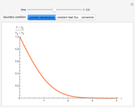 Heat Diffusion in a Semi-Infinite Region
Brian Vick Thermal Distribution in an Optical Fiber with Heat Source
Brian G. Higgins and Housam Binous Latent Heats of Fusion and Vaporization
Enrique Zeleny Heat Transfer in Fins
Rachael L. Baumann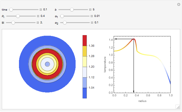 Transient Heat Conduction with a Nuclear Heat Source
Clay Gruesbeck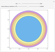 Nonsteady-State Heat Conduction in a Cylinder
Housam Binous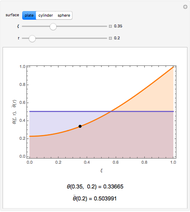 Heat Conduction in Some Standard Solids
Mikhail Dimitrov Mikhailov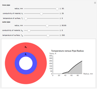 Steady-State Temperature Profile of Two-Layer Pipe
Fredericka Brown and Sara McCaslin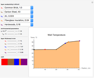 Steady-State 1D Conduction through a Composite Wall
Sara McCaslin and Fredericka Brown
-
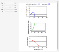 Ratkowski's Square Root Growth Rate Model for High Temperatures
Micha Peleg -
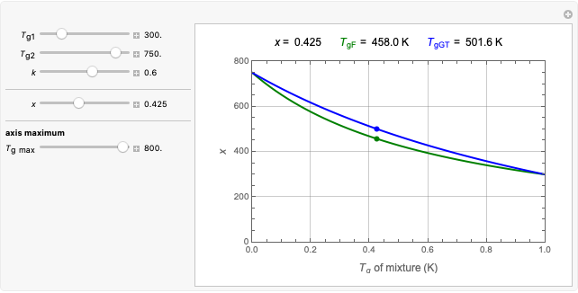 Gordon-Taylor and Fox Equations for Glass Transition Temperature
Micha Peleg -
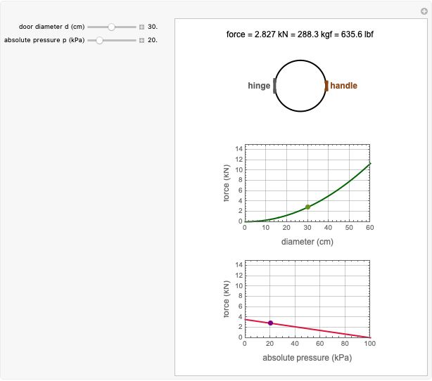 Force to Overcome Vacuum Pull
Micha Peleg -
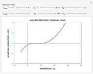 Extending the Square Root Growth Rate Model to Lethal Low Temperatures
Micha Peleg -
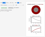 Probability of Being Strange According to Paulos
Micha Peleg -
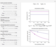
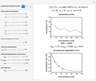 Successive Three-Point Method for Weibullian Chemical Degradation
Micha Peleg -
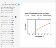 Estimating Cohesion and Tensile Strength of Compacted Powders
Micha Peleg -
 Three-Endpoints Method for Isothermal Weibullian Chemical Degradation
Micha Peleg -
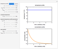
 Vitamin C Loss in Foods During Heat Processing and Storage
Micha Peleg -
 Parameterizing Temperature-Viscosity Relations
Micha Peleg -
 Laplace Distribution in Fluctuating Stock Index Records
Micha Peleg -
 Weibullian Chemical Degradation
Micha Peleg -
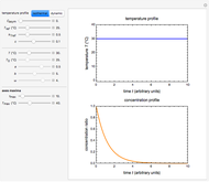 Simulating Ascorbic Acid Degradation
Micha Peleg -
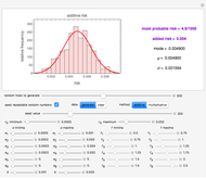 Additive and Multiplicative Risks
Micha Peleg -
 Endpoints Method for Predicting Chemical Degradation in Frozen Foods
Micha Peleg -
 Exponential Model for Arrhenius Activation Energy
Micha Peleg -
 Prediction of Isothermal Degradation by the Endpoints Method
Micha Peleg -
 Risk Guesstimation from Factor Ranges
Micha Peleg -
 Volatiles Formation Kinetics in Stored Fish
Micha Peleg -
 Comparison of Six Sigmoid Growth Curve Models
Micha Peleg