Leakage Inductance in a Transformer

Requires a Wolfram Notebook System
Interact on desktop, mobile and cloud with the free Wolfram Player or other Wolfram Language products.
Good electromagnetic coupling between the primary and secondary windings is normally achieved when the core has a high permeability. However, some leakage inductance is always present, related to transformer characteristics such as short circuit performance.
[more]


Contributed by: Y. Shibuya (September 2016)
Open content licensed under CC BY-NC-SA
Snapshots


Details
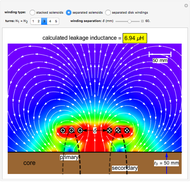
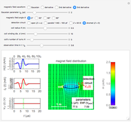
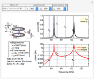
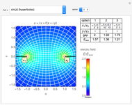
Snapshot 1: one-turn concentric windings separated by 100 mm
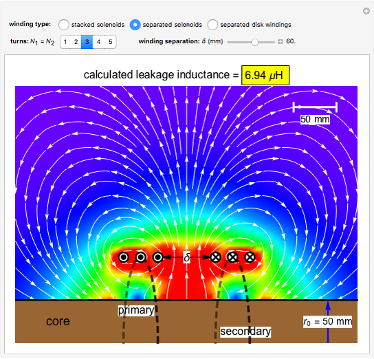
Snapshot 2: two solenoids separated by 60 mm
Snapshot 3: two disk windings separated by 80 mm
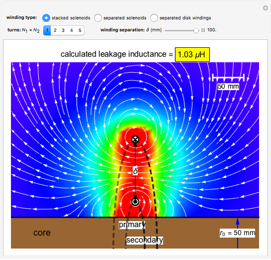
In the approximation we use, the winding ring current is accompanied by another ring current (i.e., image current) inside the core, due to its infinitely large core permeability. This approximation is by no means perfect, since the magnetic field does not intersect the core surface at right angles everywhere. Because the discrepancy occurs on the periphery, it may have a limited effect on the calculated leakage inductance.
By definition, the leakage inductance is proportional to the magnetic flux between two windings and the square of the number of turns. Calculations with a different number of turns and separation distances verify these relations.
Reference
[1] F. de Leon and A. Semlyen, "Efficient Calculation of Elementary Parameters of Transformers," IEEE Transactions on Power Delivery, 7(1), 1992 pp. 376–383. doi:10.1109/61.108931.
Permanent Citation
"Leakage Inductance in a Transformer"
http://demonstrations.wolfram.com/LeakageInductanceInATransformer/
Wolfram Demonstrations Project
Published: September 21 2016
 Induction in a Coil by a Gaussian Magnetic Field
Y. Shibuya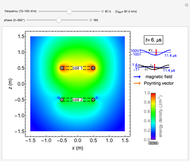 Electromagnetic Fields in Wireless Power Transmission
Y. Shibuya Electromagnetic Waves in a Cylindrical Waveguide
Y. Shibuya Electromagnetic Waves in a Parallel-Plate Waveguide
Y. Shibuya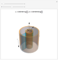 Coaxial Cable
Enrique Zeleny Vector Composition of Rotating Magnetic Fields for 3-Phase Currents
Diego M. Ferreyra and Omar D. Gallo Frequency Response of an LCR Circuit
Contributed by: Kallol Das (St. Aloysius College, Jabalpur, India) Skin Effects in Straight Wires
Y. Shibuya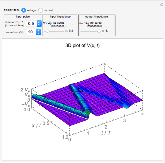 Surge Propagation in a Transmission Line
Y. Shibuya How Doorbells Work
Enrique Zeleny
-
Skin Effects in Straight Wires
Y. Shibuya -
 Leakage Inductance in a Transformer
Y. Shibuya -
 Electromagnetic Wave Scattering by Conducting Sphere
Y. Shibuya -
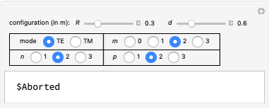 Cylindrical Cavity Resonator
Y. Shibuya -
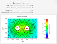 Electric Fields for Pairs of Cylinders or Spheres
Y. Shibuya -
Electromagnetic Fields in Wireless Power Transmission
Y. Shibuya -
 Wireless Power Transmission
Y. Shibuya -
Surge Propagation in a Transmission Line
Y. Shibuya -
 Electron Probability Distribution for the Hydrogen Atom
Y. Shibuya -
 Magnetic Shielding Effect of a Spherical Shell
Y. Shibuya -
 Electromagnetic Waves from a Linear Antenna
Y. Shibuya -
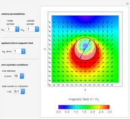 Current-Carrying Wire in Uniform Magnetic Field
Y. Shibuya -
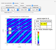 Electromagnetic Wave Incident on a Dielectric Boundary
Y. Shibuya -
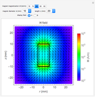 Magnetic Field and Magnetic Induction in a Cylindrical Bar Magnet
Y. Shibuya -
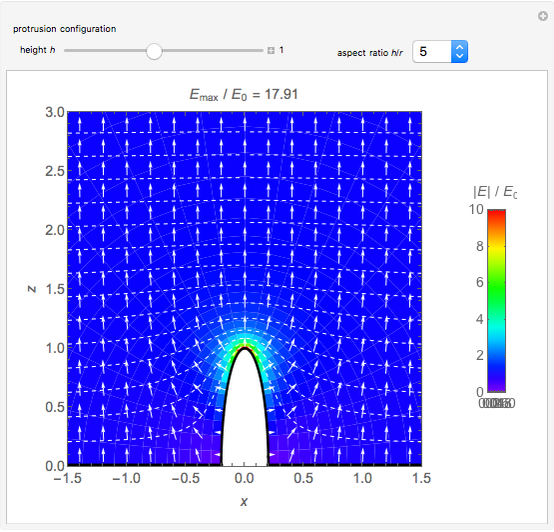 Spheroidal Protrusion in a Uniform Electric Field
Y. Shibuya -
 Electrostatic Fields Using Conformal Mapping
Y. Shibuya -
 Dielectric Sphere in a Uniform Electric Field
Y. Shibuya -
 Electromagnetic Waves in Optical Fibers
Y. Shibuya -
Electromagnetic Waves in a Cylindrical Waveguide
Y. Shibuya -
Electromagnetic Waves in a Parallel-Plate Waveguide
Y. Shibuya