Measuring Entangled Qubits


Requires a Wolfram Notebook System
Interact on desktop, mobile and cloud with the free Wolfram Player or other Wolfram Language products.
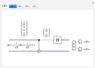
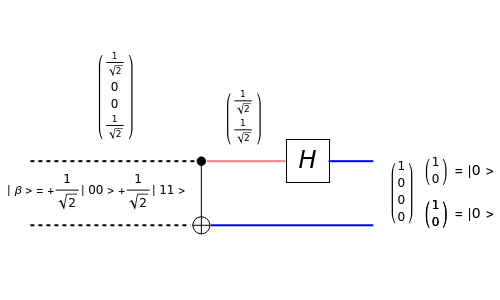
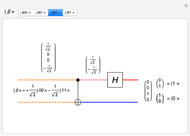
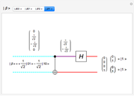
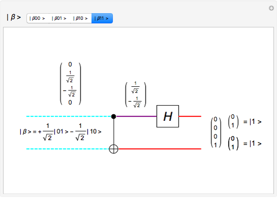
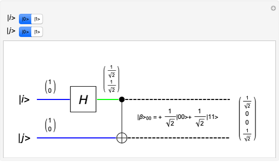
Select one of four input qubit states, each of which represents one of the Bell basis states, a type of entangled qubit pair. The quantum circuit performs a CNOT operation on the entangled pair of qubits, and then a Hadamard operation on the upper qubit. This yields a pair of classical bits, which can then be measured to identify which of the four Bell basis qubit states were input to the circuit.
Contributed by: Brad Rubin (March 2011)
Open content licensed under CC BY-NC-SA
Snapshots


Details
The CNOT (Controlled NOT) gate uses a control input (the solid black circle) to determine the target input (the XOR symbol). If the control input is  , then the target output is the same as the target input. If the control input is
  , then the target output is inverted. In this circuit, the control input is in an entangled state, being both
  and
and  at the same time (something that can occur only in quantum, not classical, computing). The Hadamard gate (the H box) is represented by the 2×2 unitary matrix
  , which takes a single qubit from the upper input and produces a single qubit output.
The intermediate state after the Hadamard operation is also displayed. Quantum wire coloring, unique for each qubit state, lets you see the qubit state as time moves from left to right. The dashed line indicates an entangled state, and common coloring indicates a common qubit state.
Reference:
P. Kaye, R. Laflamme, M. Mosca, An Introduction to Quantum Computing, New York: Oxford University Press, 2007.
Permanent Citation
"Measuring Entangled Qubits"
http://demonstrations.wolfram.com/MeasuringEntangledQubits/
Wolfram Demonstrations Project
Published: March 7 2011
 Generating Entangled Qubits
Brad Rubin Swapping Qubit States
Brad Rubin Coexistence of Qubit Effects
Peter Stano, Daniel Reitzner, and Teiko Heinosaari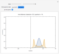 Quantum Random Walk
Tad Hogg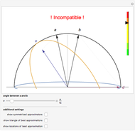 Heisenberg-Type Uncertainty Relation for Qubits
Johannes Biniok and Paul Busch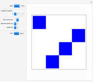 CNOT and Toffoli Gates in Multi-Qubit Setting
Rudolf Muradian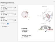 Representation of Qubit States by Probability Vectors
Sergey Filippov and Vladimir I. Man'ko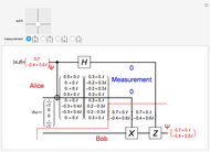 Quantum Teleportation
Brad Rubin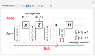 Superdense Coding
Brad Rubin Entanglement between a Two-Level System and a Quantum Harmonic Oscillator
Kwan-yuet Ho