Mohr's Circle and Stress Transformations


Requires a Wolfram Notebook System
Interact on desktop, mobile and cloud with the free Wolfram Player or other Wolfram Language products.
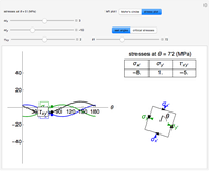
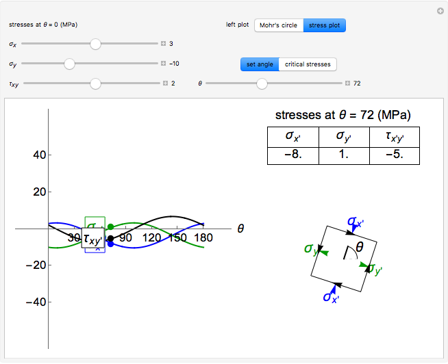
This Demonstration uses a Mohr’s circle and a stress plot to show the effects of stress transformation on a differential element or area. Use sliders to vary the stresses  ,
,  and
and  , which correspond to the stresses on the differential element at
  (dashed black line). Select "set angle" to vary the angle
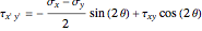
  with a slider. Stress transformation equations are used to compute the transformed stresses
  ,
,  and
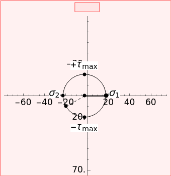
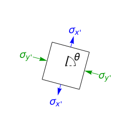
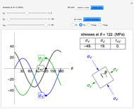
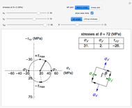
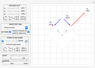
and  (solid black line), which are shown on the differential stress element as blue, green and black arrows, respectively. Select the "Mohr's circle" button to display Mohr's circle on the left. An angle of on the differential stress element corresponds to an angle of
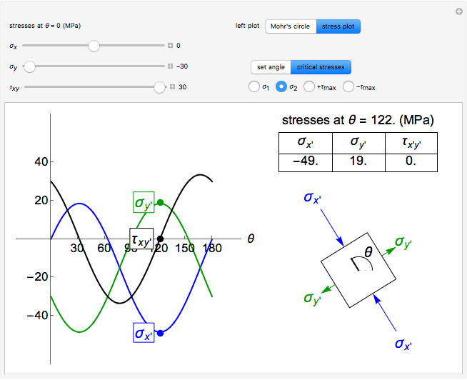
  on the Mohr's circle. Select the "stress plot" button to display a plot of all three transformed stresses versus on the left. Select "set angle" to set with a slider or "critical stresses" to snap the diagram to the angle of one of the principal stresses (
 and
and  ) or one of the maximum in-plane shear stresses (
 and
and  ). Note that Mohr’s circle is displayed with positive
  in the downward direction, so an increase in results in a counterclockwise rotation on both the Mohr's circle and the differential stress element.
Contributed by: Nick Bongiardina (October 2016)
Additional contributions by: Jeffery Knutsen, Rachael L. Baumann and John L. Falconer
(University of Colorado Boulder, Department of Chemical and Biological Engineering)
Open content licensed under CC BY-NC-SA
Snapshots

Details
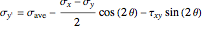
The transformed stresses are calculated from the normal stresses at :
 ,
,
 ,
,
 ,
,
where  is the average of the
  and
and  stresses, and are the normal stresses in the and directions and is the shear stress (MPa) at . Here is the angle of rotation (positive in the counterclockwise direction), and are the normal stresses in the and directions (MPa) and is the shear stress (MPa).
The principal stresses occur for  :
:
 ,
,
 ,
,
 ,
,
 ,
,
 ,
,
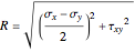
where and are the first and second principal stresses (MPa),  and
and  are the first and second principal angles and
  is the radius of Mohr's circle (MPa). By convention, the right-hand principal stress on the Mohr's circle is denoted as .
The maximum in-plane shear stress is  and the maximum shear angle is
  .
.
Reference
[1] R. C. Hibbeler, Statics and Mechanics of Materials, 4th ed., Upper Saddle River, NJ: Pearson, 2014.
Permanent Citation
 Principal Stresses and Mohr's Circle for Plane Stress
Nasser M. Abbasi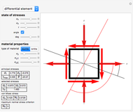 Mohr's Circle and Failure Criterion for Planar Stress States
Felipe R. Amador V.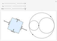 Planar Stress Rotation
Samuel Garcia Diethelm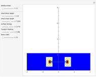 Crack Propagation and Stress Field for 2D Tensile Loads
Sam Shames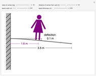 Deflection of a Diving Board
Rachael L. Baumann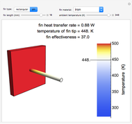 Heat Transfer in Fins
Rachael L. Baumann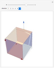 Elasticity of Shear
Enrique Zeleny Estimating Cohesion and Tensile Strength of Compacted Powders
Mark D. Normand and Micha Peleg Elastic Recovery after Plastic Deformation of Metals
Ivy Huang Crack Propagation for 2D Tensile Loading
Sam Shames
-
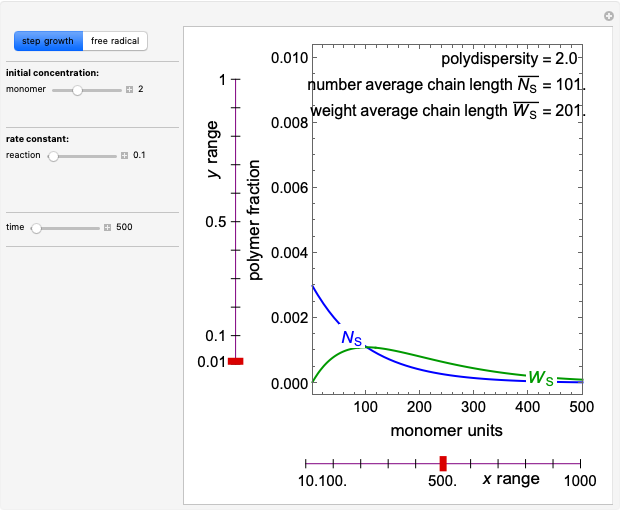 Polymerization in a Batch Reactor
Nick Bongiardina -
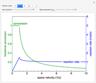 Reactor Rate and Conversion versus Space Velocity
Nick Bongiardina -
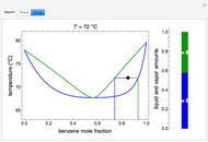 Vapor-Liquid Equilibrium Diagram for Non-Ideal Mixture
Nick Bongiardina -
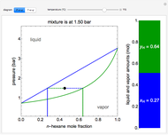 P-x-y and T-x-y Diagrams for Vapor-Liquid Equilibrium (VLE)
Nick Bongiardina -
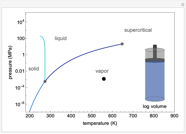 Circumnavigating the Critical Point
Nick Bongiardina -
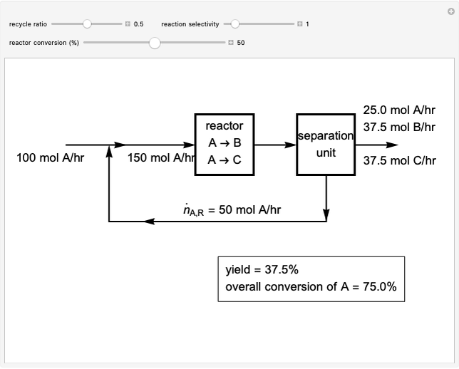 Reactor with Recycle Stream
Nick Bongiardina -
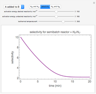 Selectivity in a Semibatch Reactor
Nick Bongiardina -
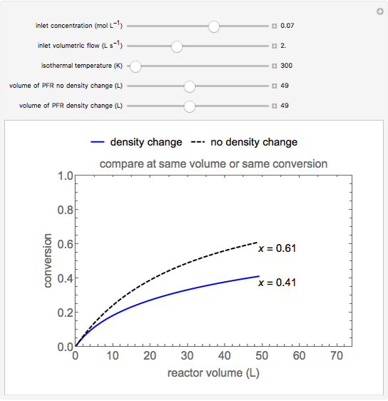 Why Density Change Cannot Be Ignored in a Plug Flow Reactor (PFR)
Nick Bongiardina -
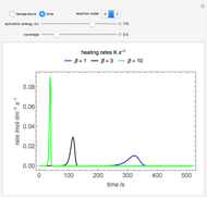 Temperature-Programmed Desorption
Nick Bongiardina -
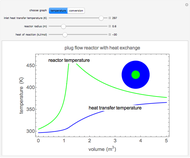 Plug Flow Reactor with Heat Transfer Jacket
Nick Bongiardina -
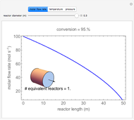 Effect of Tube Diameter on Plug Flow Reactor
Nick Bongiardina -
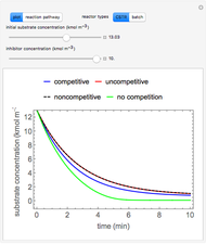 Inhibition of Enzyme Reactions in Continuous Stirred-Tank Reactor and Batch Reactor
Nick Bongiardina -
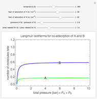 Langmuir Isotherms for a Binary Mixture
Nick Bongiardina -
 Multiple Steady States in a Continuous Stirred-Tank Reactor with Heat Exchange
Nick Bongiardina -
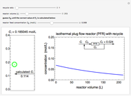 Isothermal Plug Flow Reactor with Recycle
Nick Bongiardina -
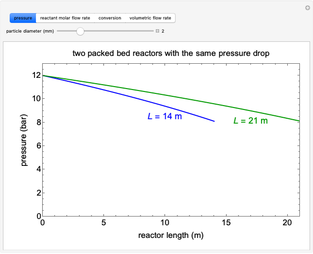 Pressure Drop in a Packed Bed Reactor (PBR) Using the Ergun Equation
Nick Bongiardina -
 Batch Reactor with Multiple Reactions
Nick Bongiardina -
 Multiple Steady States in a Continuously Stirred Tank Reactor
Nick Bongiardina -
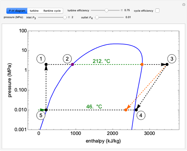 Rankine Cycle
Nick Bongiardina -
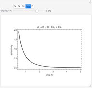 Series Reactions in a Batch Reactor
Nick Bongiardina