Swingboat Ride


Requires a Wolfram Notebook System
Interact on desktop, mobile and cloud with the free Wolfram Player or other Wolfram Language products.
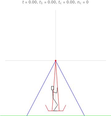
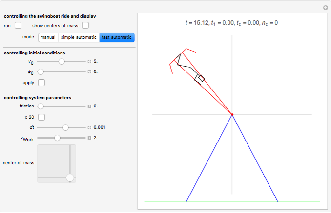
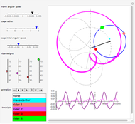
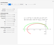
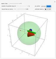
This Demonstration shows a computational model of a swingboat with rollover capability. The motions that let the rider drive the boat into rollover can be induced manually by a 2D slider or by one of two automatic modes. These show working strategies that you can compare to your manual strategies. Please note that the slowing down of screen motion that occurs during operating the 2D slider also slows down the clock  , so that the time needed to achieve the first rollover can more easily be compared to the result of an automatic run.
Contributed by: Ulrich Mutze (April 2014)
Open content licensed under CC BY-NC-SA
Snapshots
Details
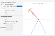
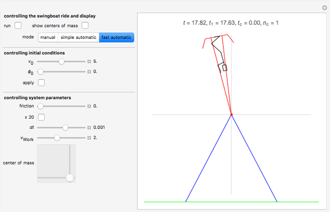
Snapshot 1: the last downswing before rollover
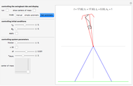
Snapshot 2: rollover just happened
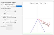
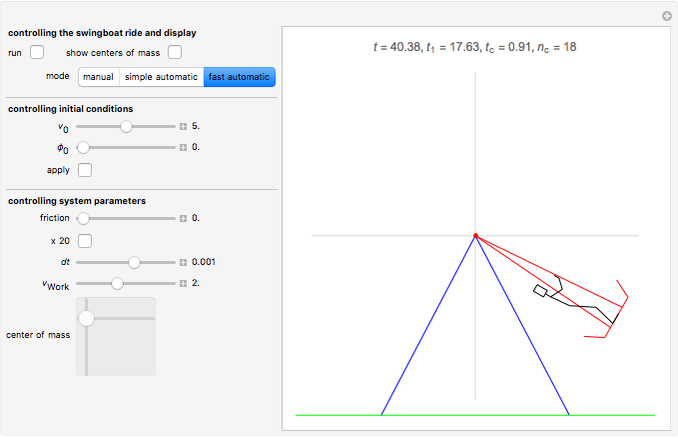
Snapshot 3: After 18 rollovers, our super-athlete has driven the boat to a speed of one cycle per 0.91 s. Actually, friction (air resistance), which is disabled for this run, would prevent such a speed.
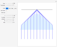
Swingboats with rollover capability are common on fairgrounds in Germany. Searching Google for "youtube Schiffschaukel Überschlag" brings up many instructive videos on how these work. What follows is a computational model of a swingboat together with a rider that you can move with a 2D slider. You can escalate the system by properly synchronizing the rider's actions to the swinging motion of the boat until it rolls over. We thus have not simply an initial value problem, but a motion problem that involves unpredictable parametric variations during motion, just as considered in control theory. This causes no difficulties, since we implement the dynamics by a time-stepping method (using a second-order Størmer–Verlet integrator) and can therefore compute the values of the relevant quantities at any step .
By storing values from the previous step, we also can determine time derivatives and thus know all quantities that determine the transition associated with the step. In our case, the equation governing this state change is the balance of angular momentum: 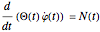 . Here
  is the angle by which the boat is deflected against the deepest point,
  is the moment of inertia of the boat and rider relative to the boat's rotation axis, and finally
  is the torque that the boat and rider feel from the Earth's gravity and from air resistance. From this equation we get
 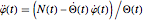 , which for given
  and
and  gives an explicit second-order ordinary differential equation for the dynamical variables . The functions and
  both are determined by the center of mass of the boat and rider system and thus, actually, by the center of mass of the rider. You can see these centers of mass by activating a checkbox.
The illustrated motion of the rider's body is highly schematic. Actually the center of mass of the human body moves with respect to its organs and bones and does not always coincide with the hip joint, as it does for our schematic rider. It would be a tempting project to build in a semi-realistic quantification of the localized strains felt by the rider and thus to allow an investigation of how to achieve rollover with the least strain. The basic principle is, of course, to place the rider's center of mass close to the axis (standing upright) during an upward swing and far away (squatting down) during a downward swing. Then the varying lever arm causes a net torque. Interestingly, the maximum energy transfer from the rider to the system takes place at the deepest point (when the rider stands up against the remarkably strong centrifugal force), when gravity exerts no torque at all.
Permanent Citation
 Scrambler Ride
Erik Mahieu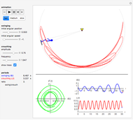 Pendulum with Varying Length or How to Improve Your Next Swing Ride
Erik Mahieu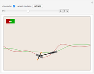 Which Way Did the Bicycle Go?
Borut Levart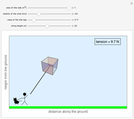 Flying a Box Kite
Jaeda C. Sichel Forces on a Roller Coaster
Ann Hsieh and Varshini Ramanathan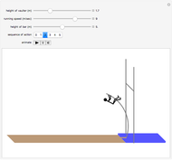 Olympic Pole Vaulting
S. M. Blinder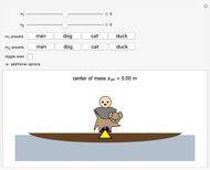 Center of Mass in a Canoe
Natalie Kadonaga Trajectory of a Golf Shot
Ryan Kauss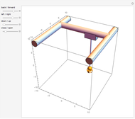 Claw Crane
Javier Pérez Fernández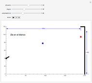 Atínale a la bola (Spanish)
Luis Jonathan Cervantes Rosas
-
 Simulating Real Gases in 2D
Ulrich Mutze -
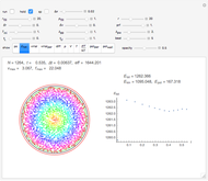
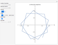
 Testing Second-Order Integrators for Motion of a Charge in a Homogeneous Magnetic Field
Ulrich Mutze -
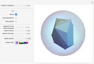 The Thomson Problem with Central Forces
Ulrich Mutze -
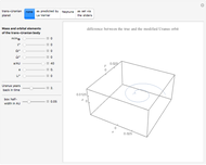
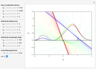 Standard Colorimetric Observer Color-Matching Functions
Ulrich Mutze -
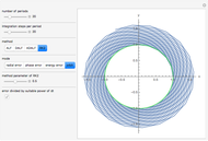
 Iteration Methods for Solving Kepler's Equation
Ulrich Mutze -
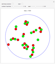
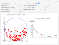 Approach of a System of Particles towards Thermal Equilibrium
Ulrich Mutze -
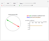 Monte Carlo Simulation of Two-Electron Spin Correlations
Ulrich Mutze -
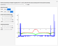
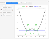 Eigenfunctions of a 1D Quantum System with Adjustable Potential
Ulrich Mutze -
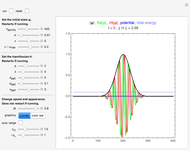 Quantum Dynamics in 1D
Ulrich Mutze -
 Lens Aberrations
Ulrich Mutze -
 On the Stability Limit of Leapfrog Methods
Ulrich Mutze -
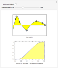 Smoothly Interpolating a Set of Data
Ulrich Mutze -
 Swingboat Ride
Ulrich Mutze -
 The Gravitational Two-Body Problem in the Einstein-Infeld-Hoffmann Approximation
Ulrich Mutze -
 Contracting the Double-Twist in SO(3)
Ulrich Mutze -
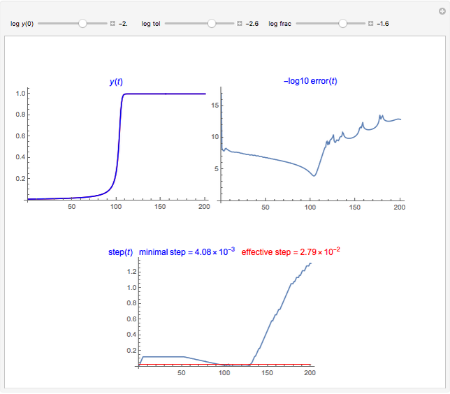 The Asynchronous Leapfrog Method as a Stiff ODE Solver
Ulrich Mutze -
 Model for Crystallization in 2D
Ulrich Mutze -
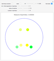 Time Evolution of a Symmetric System
Ulrich Mutze -
 Relativistic Quantum Dynamics in 1D and the Klein Paradox
Ulrich Mutze -
 The Uranus Puzzle
Ulrich Mutze