The Comet Tile


Requires a Wolfram Notebook System
Interact on desktop, mobile and cloud with the free Wolfram Player or other Wolfram Language products.
Introducing the octiamond "comet".
[more]
Contributed by: Karl Scherer, George Sicherman (June 2016)
Open content licensed under CC BY-NC-SA
Snapshots

Details
Explore: You can change and edit all diagrams to your liking.
This Demonstration is based on "Tiling Constructor Tile Dragging Variant" by the same author. The controls in both Demonstrations are very much the same.
Scientific investigations: History and new results.
In the Demonstration "Tiling Constructor Tile Dragging Variant" we asked, for several given shapes, questions like: Which of the given tilings can be extended to cover the whole plane? Here we do the same, but we focus on one tile only: the "comet" tile shown in Diagram 1, and discuss several aspects of this very special tile.
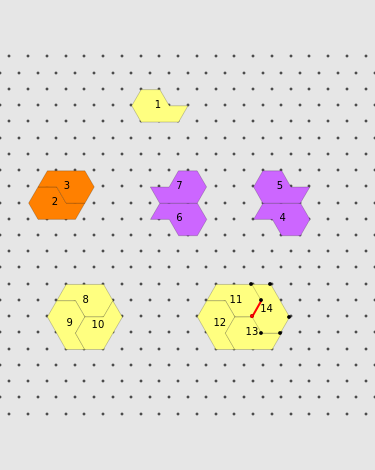
Diagram 1 This diagram shows the comet tile, which consists of eight regular triangles, and a few ways to create a cluster of tiles with two, three, or four tiles.
Diagram 2 - a simple tiling of the plane with hexagons
Two comet tiles can form a (non-regular) hexagon. Many such hexagons can be used to cover the whole plane.
Diagram 3 - introducing tilings with regular hexagons Three "comet" tiles can form a regular hexagon. Many such hexagons can be used to cover the whole plane. Can you find a plane-covering with comets which contains only one hexagon?
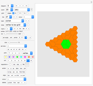
Diagram 4 - triangular formation
Many of these triangular formations can be joined to cover the plane.
Diagram 5 - triangular formation containing a hexagon
Many of these triangular formations can be joined to cover the plane.
You can also mix the formations in Diagrams 3 and 4 to find coverings of the plane with any given number of hexagonal formations. This answers the question posed above "Can you find a plane-covering with comets that contains only one hexagon?" in the affirmative: yes, we can.
Diagram 6 - expanding a single central hexagon into a larger tiling with 6-fold symmetry
This diagram starts with a hexagonal made from three comet tiles. While the whole tiling shown is 6-fold symmetrical, it is not clear whether one can extend the tiling to cover the whole plane.
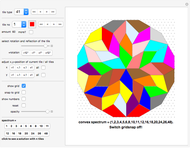
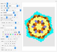
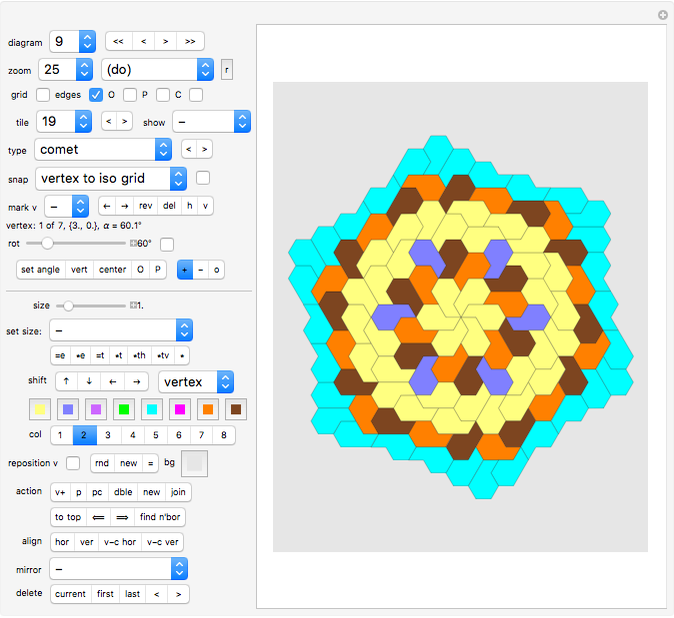
Diagram 7 - using many beautiful flowers to cover the plane
This diagram starts, exactly like Diagram 5, with a three-fold symmetrical centerpiece made from three comet tiles. This time, however, we place the many hexagons in a hexagonal grid, and we see that this can be extended to fill the plane.
The resulting pattern is especially beautiful because it shows rose-type "flowers" in a hexagonal arrangement, and in between them small green "buds", balancing nicely the bouquet of flowers with some greenery.
Diagram 8 - super large flowers also cover the plane.
This diagram is similar to Diagram 4, but more complex. The roughly hexagonal flowers again have hexagons at their center. However, this time there are no green buds (hexagons) filling the space between the large flowers. Can you find a tiling of the plane with even bigger flowers arranged on a hexagonal grid?
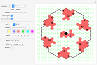
Diagram 9 - introducing tilings with 6-petal center
This diagram displays the first tiling in this Demonstration that starts from a 6-petal flower at its center. As we go outward from the center, the tiles are placed more and more chaotically. Like in Diagram 5, it is hard, if not impossible to say whether the tiling can be extended to cover the plane.
Diagram 10 - another start...
Holding on to the six-fold symmetry, but how long? Let's see...
Diagram 11...
I gave up (exhausted) at tile number 865. The six-fold symmetry is still there, but the chaos is getting bigger, too. The question of how long the six-petal center stayed was unsolved for many years, despite it being sent to many puzzlists worldwide. In May 2016, however, after sending this problem to George Sicherman, I got interested again, with the following result:
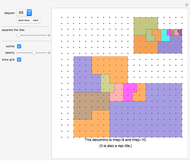
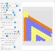
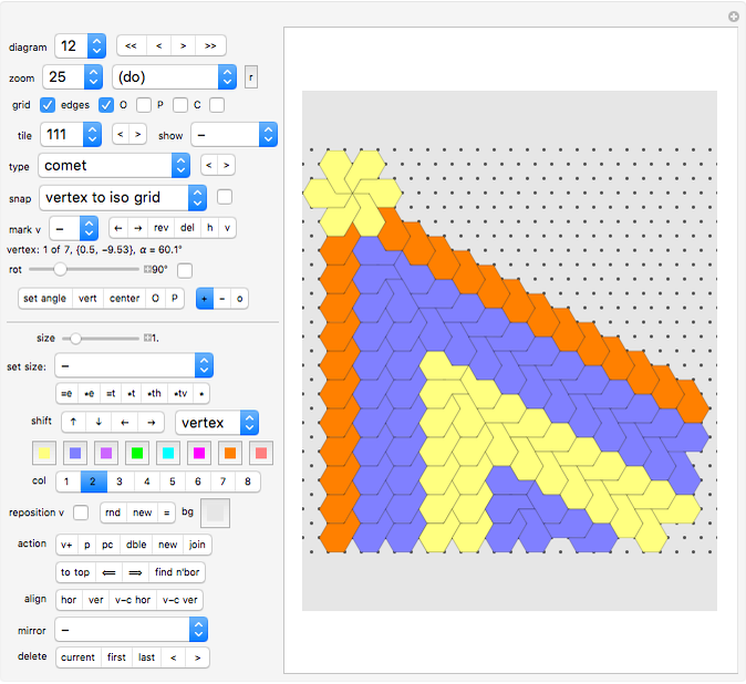
Diagram 12 - the solution!
Breakthrough! The infinite blue area can be copied and repeated forever!
======================================================================
Controls:
"project" pop-up menu and paging buttons "<,<<,>>,>"
Here you select the project (tiling) you want to see or amend.
"zoom" slider
Move the slider to the right to zoom out, to the left to zoom in.
"do" pop-up menu
The current project (tiling) can be stored, restored, added as a new project, reset to its default or "deleted" (reduced to a  square).
There are six cluster-defining options:
Option "comp all" selects all tiles as the component and stores the collection in a special storage.
Option "comp tile" selects the current tile as the component and stores it in a special storage.
Option "comp +tile" adds one tile to the existing component.
Option "comp conn." calculates the current connected component of the tiling and stores it in a special storage.
Option "comp color" selects all tiles that have the same color as the current tile and stores the collection in a special storage.
Option "comp c c" calculates the current connected component of tiles of the same color and stores the collection in a special storage.
Option "comp =
You can shift the marked cluster up, down, left, or right immediately, or you can click "add comp" first and then shift the added cluster.
Option "paint comp" paints all tiles in the component with the color of the current tile. If you want to color all tiles with a new color, select one of the colors 1 to 7 first (this will paint the current tile), then use "do paint comp" to recolor the whole component.
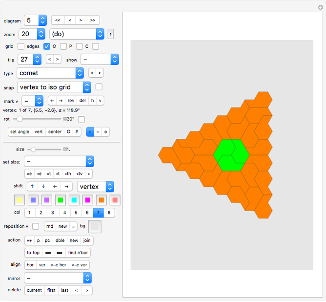
Clicking "add comp" adds a copy of the stored cluster of tiles and places it such that the red vertex of the stored component coincides with the red vertex of the current tiling. This makes it very easy to precisely place a component.
Once the cluster has been added, you can shift it to its intended place with the "shift vertex/tile/component/all" pop-up menu.
There is also an option "set opacity", to toggle the opacity between the three values 0, .5, and 1.
Finally "reset view" resets a shifted view (see "shift") to default.
"grid" toggle
If the "grid" toggle is checked, a grid of gray dots is displayed. The incremental distance between dots is 1.
There are two grids available, an orthogonal (90°) grid and an isometric (60°) grid. The grid that is displayed depends on the snap option selected.
The two snap settings "vertex to ortho grid" and "center to ortho grid" trigger the orthogonal grid.
The two snap settings "vertex to iso grid" and "center to iso grid" trigger the isometric grid to be displayed. All other snap settings leave the grid type unchanged.
Even when no grid is displayed, the snap options "vertex to ortho grid", "vertex to iso grid", "center to ortho grid", and "center to iso grid" use this grid.
"edges" toggle
Check the “edges” toggle to hide/show the edges of your tiles.
"O" (show blue origin) toggle
If the "O" toggle is checked, then the origin of the graphics area (point {0,0}) is marked by a blue dot.
"P" (show green pivot) toggle
Next is a button that triggers the display (as a green dot) of the current pivot. The pivot is used to automatically create circular arrangements of tiles (see "set angle/vert/center/O/P" setter bar and actions "p" and "pc" below).
"C" (show polygon center) toggle
This button triggers the display (as a purple dot) of the center of the current polygon.
Tile number drop-down menu
Select a sequence number to make another tile the current one. The current one will have the vertices marked by black and red dots.
Setter bar "<,>"
Allows you to select the previous or next tile of your project.
Tile type selection
The "type" drop-down menu lets you select the type of tile you want to create (like "regular triangle", "square", etc.).
All 62 irreptiles from the Demonstration "Irreptiles" are included here! Have a look to learn how these tiles tile themselves.
While the tile type is stored with each created tile, after editing the tile the displayed type text might not describe the actual tile anymore. For example, if you delete a vertex from a square, the tile is a triangle, but the stored type text will still say "square". This will not affect your creations though.
Depending on the selected tile type, the system suggests a rotation amount (see "rot" slider below). For squares the rotation is set to 45°, for hexagons to 30°, for regular pentagons to 36°, for regular octagons to 22.5°.
"<", ">" setter bar
Clicking "<" brings up the previous tile type, and ">" brings up the next tile type. Hence these buttons allow you to skim through the available tile types without picking them one by one from the long list of the drop-down menus.
"show" nr/n2/vx/v2/centers/comp pop-up menu
Select "nr" to display the sequence numbers of the tiles in small format.
Select "n2" to display the sequence numbers of the tiles in larger format.
Select "vx" to display the number of vertices of each tile in small format.
Select "v2" to display the number of vertices of each tile in larger format.
Select "centers" to mark the centers of all tiles with green dots.
Select "comp." to mark the centers of all tiles of the cluster (with a green dot at their centers), if you have defined a cluster beforehand.
"snap" pop-up menu
With the options in the "snap" menu you determine how the current tile (the tile with the red edge) is aligned to a grid or to existing tiles. The actual alignment is executed whenever you click the checkbox next to the menu; see its description below.
Option "vertex to ortho grid" snaps the red vertex to the orthogonal grid.
Option "vertex to iso grid" snaps the red vertex to the closest point of the isometric grid.
Option "vertex to vertex" snaps the red vertex to the closest vertex of any other tile.
Option "edge to edge" snaps to the nearest vertex, and also rotates the tile to an existing edge. The rotation uses the red vertex as a pivot and rotates the red edge to the edge of the other tile that is at rest. Sometimes the tile needs a further rotation by 180° around the current vertex.
This "edge to edge" snap helps you to neatly join a tile to an existing configuration. It helps to first select the best-fitting red vertex with "next". If you imagine that the current tile is shifted to its target, the red edge should not point into the interior of the second tile that you want to join to.
However, even then this feature does not always work as intended. If the edges are not joined after the move, clicking the red vertex often joins them. Sometimes additional rotation of the current tile around the red vertex might be necessary (set snap to "vertex to vertex" for this).
Option "vertex to center" snaps the red vertex to the nearest center of a tile.
Option "center to center" snaps the center of the current tile to the nearest center of a tile.
Option "center to o. grid" snaps the center of the current tile to the closest point of the orthogonal grid.
Option "center to i. grid" snaps the center of the current tile to the closest point of the isometric grid.
Option "center to vertex" snaps the center of the current tile to the nearest vertex of any another tile.
"snap" toggle
Click the unchecked box next to the "snap" pop-up menu to snap a tile.
There is no automatic snapping in this Demonstration. You have to check the box whenever you want the snap executed for the current tile.
"mark v" pop-up menu (-/s/m/l)
Here you control whether the vertices of the current tile should be marked with black and red dots. The red dot is the "handle" of the current tile. Also, the edge that starts at the red vertex is painted red.
The choices "s", "m", or "l" cause the vertices to be marked by small, medium, or large dots.
For practical reasons the marking of the vertices is switched on automatically when you click certain buttons.
" /
/ /rev/del/h/v" setter bar
Clicking "" causes the next vertex and edge of the current tile to turn red and be the new handle of the current tile. Markers will be made visible if they were switched off.
Clicking "←” causes the previous vertex of the current tile to turn red. Markers will be made visible if they were switched off.
Click “rev” to reverse the sequence of vertices of the current tile.
Click "del" to delete the vertex marked by the red dot. If no markers were visible, the option "mark vertices" will be switched on automatically. "delete" has no effect if only three vertices are left.
Click "h" to rotate the red edge to a horizontal position.
Click "v" to rotate the red edge to a vertical position.
Vertex sequence number, position, angle
The next line on the left border shows the sequence number and position of the red vertex and the angle  between the tile's two edges meeting at this point.
"angle at red vertex"
You are shown the angle at the vertex that is colored red (if option "mark vertices" is active).
"rot" slider (rotation / angle)
You can set the rotation increment or angle to any value between .1° and 360°.
"rot" angle toggle
Each tile type has several angle values associated with it, which can be called up by clicking the "rot" toggle repeatedly. This avoids the manual input of several angle or rotation values.
"set angle / vert / center / O / P" setter bar
Clicking "set angle" will set the angle at the red vertex to the value given by the "rot" slider. The red edge will be rotated around the red vertex in the process.
Click "vert" (vertex) to rotate the current tile by the set rotation increment around the red vertex.
Click "center" to rotate the current tile by the set rotation increment around the center of the tile.
Click "O" to rotate the current tile by the set rotation increment around the origin (which is at the center of the graphics area).
Click "P" to rotate the current tile by the set rotation increment around the green pivot (which is at the origin and can be set by the action button "p" to any other position).
"+/-/o" setter bar
This setter bar lets you select whether the rotations (angle/vertex/center/O/P) just described are counterclockwise ("+") or clockwise ("-").
If "o" is selected, this triggers the powerful "create a ring of tiles" feature for the "vertex/center/O/P" buttons, see above. This create a ring of tiles feature often dramatically simplifies the creation of mosaics. In the kites/darts mosaic, for example, you can create circular formations of five darts or five kites around one vertex or around the origin with one click of the "vertex" button.
"size" slider
Here you set a value between 0.01 and 10. The value will be used by the buttons of the following setter bars.
"set size" pop-up menu
Here you select from several special values for the "size" slider. Among others, the golden ratio and several square roots are provided. You can also multiply the size by certain fixed values.
You can also store and restore the current slider value, and measure the length of the current (red) edge.
Finally, option "add edge" adds the length of the current edge to the current "size" slider value. The polygon stays unchanged.
"=e/*e/=t/*t/*th/*tv/*" setter bar
Clicking button "=e" will modify the current tile such that the length of the red edge is equal to the value of the "resize" slider. The red vertex will stay put.
Clicking button "*e" will modify the current tile such that the length of the red edge is equal to its old length multiplied by the value of the "resize" slider. The red vertex will stay put.
Clicking button "=t" changes the size of the current tile such that the current (red) edge has the length given by the "resize" slider. The current vertex will stay put.
Clicking button “*t” changes the size of the current tile by the factor given by the “resize” slider. The current vertex will stay put.
Clicking button "*th" stretches the current tile horizontally. The center of the tile will stay put.
Clicking button "*tv" stretches the current tile vertically. The center of the tile will stay put.
Clicking button "*" resizes the whole tiling, with the center of the board (the origin) being the fixed point.
"shift" setter bar
Click one of the buttons to shift the current tile (or view or component or project) to the north, south, west, or east. The amount of shifting is given by the "size" slider. On the isometric grid up and down shifts are done in grid steps ("size 1" => shift = sqrt[3]/2).
During "reposition v" mode (i.e., repositioning of the red vertex) clicking the buttons will shift the red vertex instead.
"view/vertex/tile/component/project" setter bar
Select "vertex" to make the buttons in the "shift" setter bar apply to the current vertex.
Select "tile" to make the buttons in the "shift" setter bar apply to the current tile.
Select "comp." to make the buttons in the "shift" setter bar apply to the current component.
Select "project" to make the buttons in the "shift" setter bar apply to all tiles simultaneously.
Note that the amount of shifting is controlled by the "shift" slider and the "set size" pop-up menu (see above).
Color swatches
There are eight color selectors. Click the colored squares to pick new colors.
"col" color application setter bar
Click one of the eight buttons "1" to "8" to color the current tile with one of the eight colors.
On the left (in brackets) the color number of the current tile is displayed.
"reposition v" toggle
While "reposition v" (repositioning of the red vertex) is active, you can change the position of the red vertex.
You can select any vertex to be the red vertex by cycling through the vertices by clicking " " or "
 " of the "//rev/del/h/v" setter bar.
You can also delete a vertex (button "delete"), add a vertex (button "v+"), apply a color, or create a copy of the tile (button "double") while you are in repositioning mode. When you click button "v+", a new vertex will be inserted at the center of the red edge.
During repositioning mode, clicking one of the "shift" buttons will only shift the red vertex, not the whole tile.
Note that most other options are unavailable while in repositioning mode (such as save/restore). Also, all action, align, mirror, and delete options are inactive (apart from action buttons "v+", "double", and "new").
Once you are finished redesigning your tile, click the toggle again to go back to tile-dragging mode.
"rnd/new/=" setter bar
Click button "rnd" to randomly color all tiles with one of these eight colors.
Click button "new" to create a new set of eight random colors.
Click button "=" to color all tiles of the same tile type (as the current tile) with the color of the current tile.
Background color
In the same row there is a color swatch for the background color. Click it to change the background color.
"action" setter bars
Click "v+" to create an additional vertex between the red vertex and the vertex following it.
Click "p" (pivot) to set the green pivot point (used for rotations) to the current position of the red vertex.
Click "pc" (pivot at center) to set the green pivot point (used for rotations) to the center of the current tile.
Action "dble" (double) places a copy of the current tile on the board at the current position.
Action "new" creates a new copy of the currently selected tile type. If you haven't altered the previous tile, "new" has the same effect as clicking "dble".
Action "join" joins two tiles that have an edge in common (if that edge is marked red).
Action "to top" renumbers the tiles such that the current one is the last in the sequence and hence will be displayed on top of any other tile (if they overlap).
Action " " makes the previous tile the current one.
Action "⟹" makes the next tile the current one.
Action "find n'bor" finds the closest neighbor, that is, it finds the tile that is "snap-closest" to the current tile and makes this the new current tile. Here the snap-closest tile is the closest tile with regard to the setting chosen for the snap function.
If nothing ("-") or "vertex to ortho grid", "vertex to iso grid", "edge to edge", or "vertex to vertex" has been selected for snap, then the new current tile is the one that has a vertex closest to the current red vertex.
If "vertex to center" has been selected for snap, then the new current tile is the one that has its center closest to the current red vertex.
If "center to center" has been selected for snap, then the new current tile is the one that has its center closest to the current center.
If "center to vertex" has been selected for snap, then the new current tile is the one that has a vertex closest to the center of the current tile.
"align" setter bars
Button "hor" (align horizontal) rotates the current tile such that the red edge is horizontal.
Button "ver" (align vertical) rotates the current tile such that the red edge is vertical.
Button "v-c hor" rotates the current tile such that the (imaginary) line through the red vertex and the center of the tile is horizontal.
Button "v-c ver" rotates the current tile such that the (imaginary) line through the red vertex and the center of the tile is vertical.
"mirror" pop-up menu
Select "horiz. (vertex)" to mirror the current tile at an imaginary horizontal line through the red vertex.
Select "horiz. (center)" to mirror the current tile at an imaginary horizontal line through the center of the tile.
Select "horiz. (origin)" to mirror the current tile at an imaginary horizontal line through the origin.
Select "horiz. (pivot)" to mirror the current tile at an imaginary horizontal line through the (green) pivot.
Select "vertic. (vertex)" to mirror the current tile at an imaginary vertical line through the red vertex.
Select "vertic. (center)" to mirror the current tile at an imaginary vertical line through the center of the tile.
Select "vertic. (origin)" to mirror the current tile at an imaginary vertical line through the origin.
Select "vertic. (pivot)" to mirror the current tile at an imaginary vertical line through the pivot.
Select "at edge" to mirror the current tile at the red edge.
Selecting "perpend. to edge" mirrors the current tile at the (imaginary) line through the red vertex and perpendicular to the red edge.
Select "at vertex" to rotate the tile by 180° around the red vertex.
Select "at center" to rotate the tile by 180° around the tile center.
Select "at origin" to rotate the tile by 180° around the origin.
Note: if you want to keep the unmirrored tile, click "double" first.
Also note that if the sequence of vertices was clockwise, then the new tile has its vertices ordered counterclockwise.
Click "all at origin (1)" to mirror all tiles at the origin.
Select "all at origin (2)" to create additional copies of all existing tiles and mirror them at the origin. This way you only have to create half of a point-symmetrical tiling before you create the second half with "all at origin (2)".
Similarly: options "all at pivot (1)" and "all at pivot (2)".
"delete" setter bar
You can delete the current tile (button "current"), the first tile (button "first"), the last tile (button "last"), all tiles in the current component (button "comp"), or all tiles having a sequence number lower ("<") or higher (">") than the current tile. You cannot delete the last remaining tile.
History
This Demonstration is based on "Tiling Constructor Tile Dragging Variant" by the same author. The controls in both Demonstrations are very much the same.
Contributors: George Sicherman (Diagrams 3 and 4).
Permanent Citation
 Tiling Constructor, Tile-Dragging Variant
Karl Scherer Regular Tilings
Karl Scherer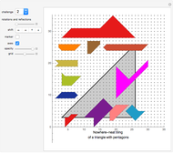 Nowhere-Neat Tilings
Karl Scherer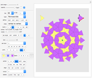 Tiling Constructor
Karl Scherer Nowhere-Neat Tilings of the Plane
Karl Scherer Neat Alternating Tilings of the Plane
Karl Scherer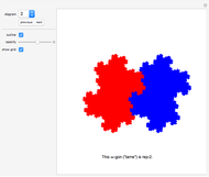 Rep-Tiles
Karl Scherer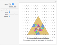 Irregular Tilings
Karl Scherer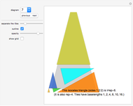 Perfect Tilings
Karl Scherer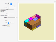 3D Rep-Tiles and Irreptiles
Karl Scherer