AC Thyristor Trigger Angle versus Power Factor


Requires a Wolfram Notebook System
Interact on desktop, mobile and cloud with the free Wolfram Player or other Wolfram Language products.
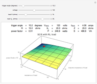
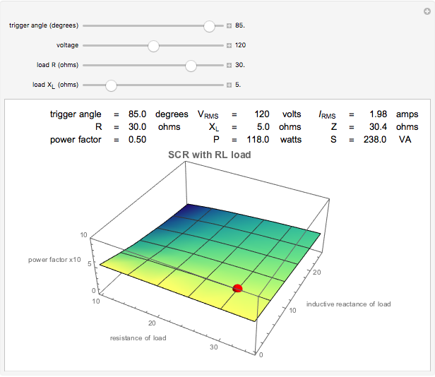
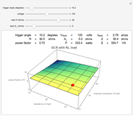
This Demonstration allows you to manipulate a simple SCR circuit incorporating a resistive and an inductive load. You can view the interaction of each of the adjustable parameters graphically. The red ball represents the point of operation for any given set of parameters.
Contributed by: Harley H. Hartman (March 2011)
Open content licensed under CC BY-NC-SA
Snapshots


Details
The RMS current is calculated using the following formula:  , where
  is the trigger angle,
  is the load resistance,
  is the load inductive reactance, and
  is the supply voltage.
Equations and principles referenced from D. Hart, Introduction to Power Electronics, Upper Saddle River, NJ: Prentice Hall, 1997.
Permanent Citation
"AC Thyristor Trigger Angle versus Power Factor"
http://demonstrations.wolfram.com/ACThyristorTriggerAngleVersusPowerFactor/
Wolfram Demonstrations Project
Published: March 7 2011
 AC Thyristor Operation
Harley H. Hartman Pulse Width Modulation Principle
Harley H. Hartman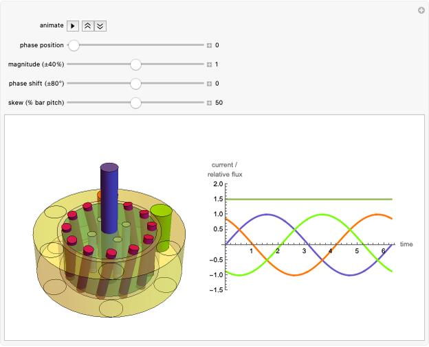 Operating an AC Three-Phase Induction Motor
Harley H. Hartman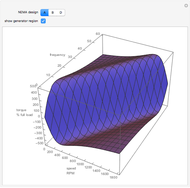 AC Induction Motor VFD Operation
Harley H. Hartman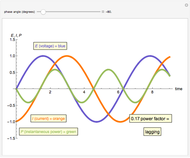 AC Power Factor Principle
Harley H. Hartman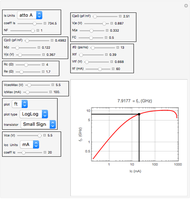 Small Signal (AC) Bipolar Parameters from SPICE Parameters
Allen Hollister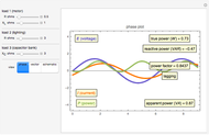 Simulating the Power Factor of an AC System
Harley H. Hartman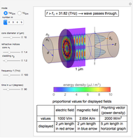 Electromagnetic Waves in Optical Fibers
Y. Shibuya Torque and Speed Characteristics of Separately Powered DC Motors
Anping Zeng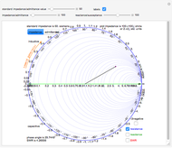 Engineering-Style Smith Chart
Randolph J. Herber, W9HE
-
 AC Thyristor Trigger Angle versus Power Factor
Harley H. Hartman -
Operating an AC Three-Phase Induction Motor
Harley H. Hartman -
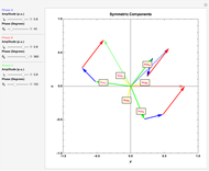 Fortescue's Theorem for a Three-Phase Unbalanced System
Harley H. Hartman -
 AC Rotating Magnetic Field Principle
Harley H. Hartman -
Simulating the Power Factor of an AC System
Harley H. Hartman -
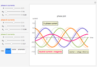 Simulating the Neutral Current of an AC System
Harley H. Hartman -
AC Power Factor Principle
Harley H. Hartman -
AC Induction Motor VFD Operation
Harley H. Hartman -
Pulse Width Modulation Principle
Harley H. Hartman -
AC Thyristor Operation
Harley H. Hartman -
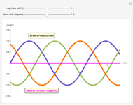 AC Three-Phase Neutral Current
Harley H. Hartman -
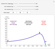 AC Induction Motor Rotor Design
Harley H. Hartman -
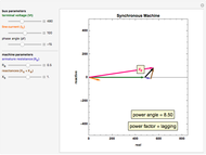 AC Synchronous Machine Vector Diagram
Harley H. Hartman