Applications of Fresnel Equations for Light Intensities

Requires a Wolfram Notebook System
Interact on desktop, mobile and cloud with the free Wolfram Player or other Wolfram Language products.
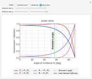
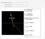
This Demonstration shows the change of light intensity when light passes between two dielectric media, making use of the Fresnel equations.
[more]
Contributed by: Han Wang (February 2013)
With additional contributions by: Cheng Zhen
(University of Science and Technology of China)
Open content licensed under CC BY-NC-SA
Snapshots
Details
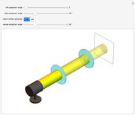
The blended color of reflected or transmitted light shown in the graphic could be more red or more yellow than the incident light, in accordance with the Fresnel equations showing the difference of power reflection and power transmission coefficients in two light beams.
We can observe directly that the closer the incident angle is to the Brewster angle, the more red the reflected light becomes, until there is no yellow light in the reflected light at the Brewster angle. This is consistent with the Fresnel equations for the polarization of light reflected at the Brewster angle.
Another interesting thing to try is to move the locator so that the incident angle is close to zero or  . You can then observe the cases of vertical incidence and grazing incidence. Moving the three sliders will reveal these differences.
This Demonstration can also be used to exhibit Snell's law, relating the angles of incidence and refraction.
The subscripts "s" and "p" refer to the two directions: perpendicular or parallel to the plane of incidence; the subscripts "r" and "t" refer to "reflection" and "transmission"; other symbols used are defined as follows:
Ip: intensity of the light parallel to the plane of incidence
I: total light intensity
 : refractive index of the incident media
 : refractive index of the refractive media
 : incident angle
 : refraction angle
 : electric fields of the reflected light perpendicular to the plane of incidence
 : electric fields of the reflected light parallel to the plane of incidence
 : electric fields of the transmitted light perpendicular to the plane of incidence
 : electric fields of the transmitted light parallel to the plane of incidence
 : electric fields of the incident light perpendicular to the plane of incidence
 : electric fields of the incident light parallel to the plane of incidence
Permanent Citation


