Directivity Pattern of Line Arrays

Requires a Wolfram Notebook System
Interact on desktop, mobile and cloud with the free Wolfram Player or other Wolfram Language products.
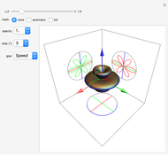
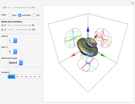
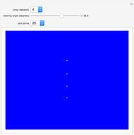
Highly directional acoustic and electromagnetic antennae are often built from linear arrays of omnidirectional transmitting (or receiving) elements. This Demonstration plots the directivity pattern of an unshaded line array of  omnidirectional elements, steered to the angle
  with respect to the array axis. The patterns have cylindrical symmetry about the array axis. The array elements are plotted as white dots to show their number and orientation. An even number of elements results in a null along the axial direction of the array. An odd number of elements results in an endfire sidelobe, which, for many applications, is undesirable. The directivity pattern can be regarded as a transmission or reception sensitivity pattern.
Contributed by: Christopher Purcell (March 2011)
Open content licensed under CC BY-NC-SA
Snapshots
Details
The directivity pattern of an  -element unshaded line array is given by
  , where
  , the wave number
  ,
,  is the polar angle,
  is the steering angle, and
  is the wavelength. The frequency is
  Hz and the array inter-element spacing is
  meters. The wave speed is
  m/s. In this Demonstration, the inter-element spacing is
  . You can vary the number of elements
  in the range 1 to 16, the steering angle
  in the range -90 to 90 degrees, and the number of points plotted in the azimuthal direction. The array elements are plotted as white dots.
Permanent Citation


