Operating an AC Three-Phase Induction Motor


Requires a Wolfram Notebook System
Interact on desktop, mobile and cloud with the free Wolfram Player or other Wolfram Language products.
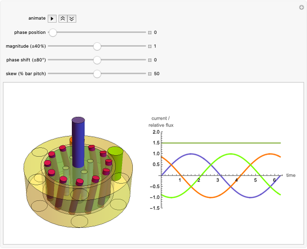
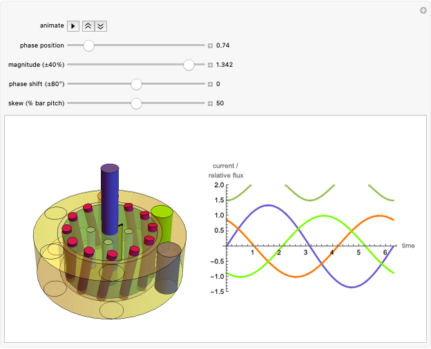
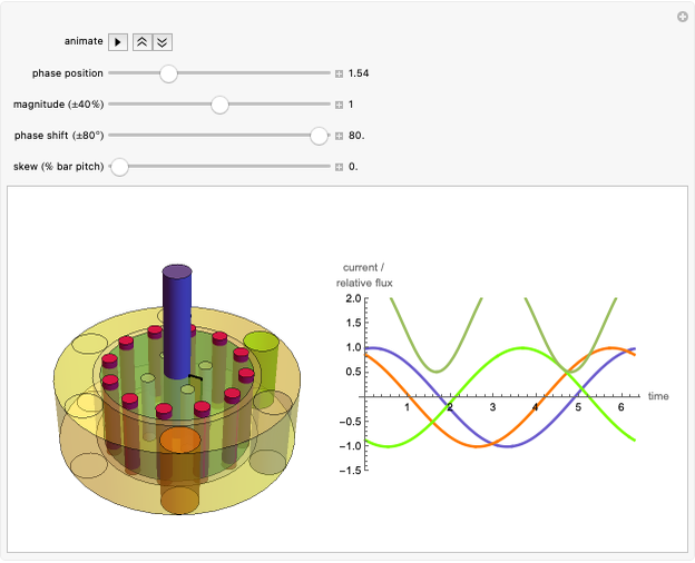
This Demonstration illustrates the operation of an induction motor. You can create a voltage imbalance or a phase shift in the three-phase source. This will result in a change in speed of the rotor that represents a change in developed torque. You can also adjust the skew of the rotor bars.
Contributed by: Harley H. Hartman (June 2008)
Open content licensed under CC BY-NC-SA
Details
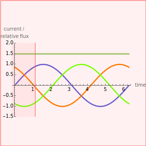
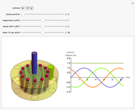
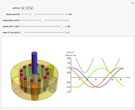
The 3D graphic display represents a rotor and a stator of an induction motor. Also shown is a plot of the three\[Hyphen]phase supply. The rotor illustrates the rotor bars and other major parts of a typical induction motor rotor. The stator shows six phase bands representing each of the winding sides of a typical two-pole machine. The phase bands illuminate when the phase polarity is positive. This provides a visualization of the rotating nature of the created magnetic field. The rotor speed is controlled by the magnitude of the magnetic field. If you adjust the controls such that the magnetic field magnitude is not consistent, the rotor will slow down and speed up in relation to the field. This illustrates the change in torque that results in an induction motor under similar circumstances. This effect is exaggerated to allow this phenomenon to be observed.
Snapshots

Permanent Citation
 AC Induction Motor Rotor Design
Harley H. Hartman AC Induction Motor VFD Operation
Harley H. Hartman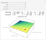 AC Thyristor Trigger Angle versus Power Factor
Harley H. Hartman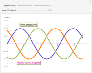 AC Three-Phase Neutral Current
Harley H. Hartman AC Thyristor Operation
Harley H. Hartman AC Synchronous Machine Vector Diagram
Harley H. Hartman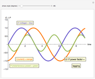 AC Power Factor Principle
Harley H. Hartman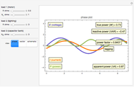 Simulating the Power Factor of an AC System
Harley H. Hartman AC Rotating Magnetic Field Principle
Harley H. Hartman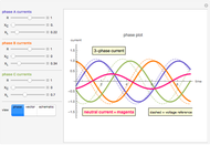 Simulating the Neutral Current of an AC System
Harley H. Hartman
-
 Operating an AC Three-Phase Induction Motor
Harley H. Hartman -
AC Thyristor Trigger Angle versus Power Factor
Harley H. Hartman -
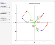 Fortescue's Theorem for a Three-Phase Unbalanced System
Harley H. Hartman -
AC Rotating Magnetic Field Principle
Harley H. Hartman -
Simulating the Power Factor of an AC System
Harley H. Hartman -
Simulating the Neutral Current of an AC System
Harley H. Hartman -
AC Power Factor Principle
Harley H. Hartman -
AC Induction Motor VFD Operation
Harley H. Hartman -
 Pulse Width Modulation Principle
Harley H. Hartman -
AC Thyristor Operation
Harley H. Hartman -
AC Three-Phase Neutral Current
Harley H. Hartman -
AC Induction Motor Rotor Design
Harley H. Hartman -
AC Synchronous Machine Vector Diagram
Harley H. Hartman