Constructing and Manipulating Graphs


Requires a Wolfram Notebook System
Interact on desktop, mobile and cloud with the free Wolfram Player or other Wolfram Language products.
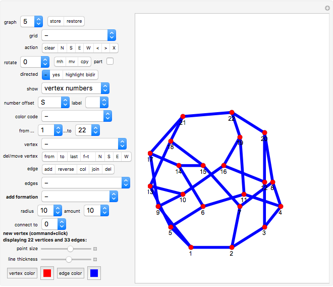
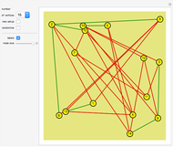
This Demonstration lets you create and manipulate any undirected and directed graphs (including even bidirectional arrows and loops).
[more]
Contributed by: Karl Scherer (January 2009)
Additional contributions by: Ed Pegg Jr
Open content licensed under CC BY-NC-SA
Snapshots


Details
Motivation
While there are already many other Demonstrations about two-dimensional graphs, none of them allows you to freely create, color, and manipulate graphs.
Basic options
The options "store" and "restore" allow you to keep a backup version of your graph in memory. Note that the default setup is already stored in the backup (hit "clear" and then "restore" to test it).
"clear":
You cannot delete the last vertex. Therefor hitting "clear" leaves only one vertex in the lower left corner.
The options "N","S","E","W" shift the whole graph (or part of it, if "part" is active) to the North, South, East or West, one unit at a time.
The option "<" decreases the size of the graph by ten percent; the option ">" enlarges it.
You can add a new vertex at any time with Command+Click (Alt+Click on Windows or Option+Click on the Mac). You can also delete an existing vertex with Command+Click.
Warning: Do not create new vertices too quickly, since this can lead to system errors.
The option "X" switches the display of the axes on and off.
The drop-down menu "rotate" lets you rotate the graph around the "from" vertex.
The "grid" drop-down menu options let you choose between a rectangular grid and an isometric grid (the latter allows regular triangles and hexagons to be drawn since snap points are distanced accordingly).
The "rotate" control
Select a rotation to rotate your graph around the "from" vertex.
To rotate relative to the center of your graph, create the center first (select vertex/create center) and make it the "from" vertex.
If "part" is active, only the connected part (which contains the "from" vertex) is rotated.
mirror/copy control "mh/mv/cpy"
"mh" (mirror horizontally): You can mirror your graph horizontally (mirror relative to vertical line through the "from" vertex).
"mv" (mirror vertically): You can mirror your graph vertically (mirror relative to horizontal line through the "from" vertex).
To mirror relative to the center, create the center first (select vertex/create center) and make it the "from" vertex.
If "part" is active, only the connected part (which contains the "from" vertex) is mirrored.
"part" checkbox
If "part" is active, only the connected part which contains the "from" vertex will be rotated, mirrored or shifted (see above).
The "directed" control
Select "yes" to show arrows. (See "edges" below to find out how to create bidirectional arrows).
Select "highlight bidir" to additionally display all bidirectional arrows in red color.
(You add/delete bidirectionality of an edge with "edge" option "add".)
Notation (the "show" option)
Here you can select several types of notation or labels for the vertices and edges.
The option "vertex labels" displays text for each vertex; this text can be edited with the "label" feature (see below).
You can show the "degrees" of the vertices; the degree of a vertex is the number of edges connected to it.
With "distance (vertex)" you can show the graph distance (degree of separation) of each vertex in relation to the selected "from" vertex. Note that the degree of separation on a directed graph is different from the one on an undirected graph (click "directed" to switch between these cases).
The option "edge numbers" will show the edge numbers at the center of the edges.
The option "distance (edge)" shows how far an edge is from the "from" vertex. (The distance of an edge is calculated as the minimum of the distances of its endpoints).
The option "number offset" lets you choose where the notation should be in relation to the vertices and edges (North, South, etc).
Editing vertex labels
Select the option "show vertex labels" first. Select the vertex whose label you want to edit ("from" parameter).
Now selecting the label option "-" deletes the vertices' label. The option "=" deletes all labels. The option "+" copies the label of the "from" vertex to all vertices without a label. Selecting a letter will cause the letter to be joined to the end of the label word, as a typewriter would.
Color code pop-up menu
The option "degree (vertex)" color-codes all vertices according to their degree, that is, by the number of edges converging to the vertex (the degrees 0, 1, 2, 3, 4, 5, 6, >6, correspond to the colors red, orange, green, cyan, blue, purple, gray, black).
The option "distance (vertex)" color-codes all vertices according to their graph-distance from the "from" vertex (the distances 0, 1, 2, 3, 4, 5, >5, ∞ correspond to the colors red, orange, cyan, green, blue, purple, gray, black).
The degree of separation on a directed graph is different from the one on an undirected graph (click "directed" to switch between these cases).
The special case ∞ (color-coded black) denotes all parts of the graph that cannot be reached at all from the "from" vertex.
The option "distance (v,e)" color-codes all vertices and edges according to their graph-distance from the "from" vertex.
The option "shortest path" finds the shortest path (if there is one) from "from" vertex to "to" vertex.
The option "short path tree" displays a tree of shortest paths from the "from" vertex to all the other vertices. The "to" parameter is ignored here.
The option "shortest loop" finds the shortest closed path (if there is one) that contains the line from the "from" vertex to the "to" vertex.
"graph tree" starts from the "from" vertex (the so-called "root" of the tree) and connects all vertices with a tree structure, i.e., a structure of vertices and lines which contains no loops. The result is best viewed with "edge color" set to white (or nearly white) since the vertices and edges belonging to the tree are painted with "vertex color".
"From" and "to" selection
Here you can select the sequential numbers of two vertices; usually the start vertex and end vertex of an edge you want to edit.
In many cases, "from" and "to" are automatically updated while you add or edit vertices. One example is the creation of new vertices with "command+click" ("alt+click" on a personal computer).
"Vertex" pop-up menu
You can create a midpoint of a line (see also "add formation" below).
You can create the center point (of the set defined by the vertices).
You can create the center of the current part (connected component which contains the "from" vertex).
The "clear" option leaves a single vertex at the bottom-left corner. You can also delete a vertex with "command + click" (alt+click on a PC) while pointing at a vertex with your cursor.
You can delete a current part (connected component which contains the "from" vertex).
You can color the "from" vertex, the "to" vertex, or the last vertex (i.e., the one with the highest sequence number).
You can also color a whole range of vertices (from "from" to "to"). You might have to switch off the automatic color coding (described above) first.
You can color all vertices of the current part (connected component which contains the "from" vertex).
You can color all vertices at once.
The "split" option splits a vertex into two vertices, with the new vertex having the same connections to other vertices.
The "unite" option unites the two vertices selected ("to" vertex moves to the position of the "from" vertex), with the new vertex having the sum of the connections.
"vertex del/move" setter bar.
First half: Delete vertex: options from/to/last/range; second half: move vertex: N/S/E/W.
"Edge" setter bar
The setter bar contains the most used options (compare the "edge" pop-up menu below).
Option "add" connects "from" vertex to "to" vertex. If the edge exists already, adding it again will made it bidirectional. Adding it again will undo the bidirectionality.
If "from" is the same as "to", adding will cause a little loop to be created. The small loop will be created using the opposite of the "number offset". Hence if "number offset" is S (South), then the loop will be to the North of the vertex. This keeps numbers and loops separate for better readability.
To reverse the direction of an arrow click "r";
Select "col" to color the current edge (given by the "from" and "to" selection).
Option "join" connects "to" vertex to nearest vertex which is not already connected to the "to" vertex.
You can delete the edge (given by the "from" and "to" selection).
"Edges" pop-up menu
You can add the edge which connects the "from" vertex with "to" vertex. Selecting "add" for an EXISTING edge switches an arrow from unidirectional to bidirectional and vice versa. (By the way: in directional graphs the edges are called "arcs".) If "from" is the same as "to", a little loop will be created. The small loop will be created using the opposite of the "number offset". Hence if "number offset" is S (South), then the loop will be to the North of the vertex. This keeps numbers and loops separate for better readability.
You can reverse the direction of an arrow, of a range of arrows (connected to "from"..."to"), or all of them. The direction of an edge is only visible when you select the "directed" option. In this Demonstration either all edges of a graph have directions or none have. A graph with directions is called a directed graph.
You can delete the current edge (given by the "from" and "to" selection).
You can color the selected edge. You might have to switch off the automatic color coding (described above) first.
You can color all edges connected to the "from" vertex.
You can color all edges of the current part (connected component which contains the "from" vertex).
You can color all edges at once.
You can delete the selected edge (given by its end points "from" and "to").
You can delete all edges connected to the "from" vertex.
You can delete all edges connected to a range of vertices (given by "from",...,"to").
You can delete all edges of the current part (connected component which contains the "from" vertex).
You can also delete all edges.
You can create a chain of edges, connecting vertex 1 to vertex 2, vertex 2 to vertex 3 etc.
You can delete such a chain (or any edges that would be part of such a chain).
"Add formation" pop-up menu
The options "midpoints from-to" adds one or more ("amount") equidistant vertices to the existing edge given by the "from" and "to" parameters. The parameter "radius" is not used for the midpoints.
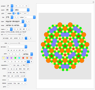
Often graphs in science are presented as a linear or circular arrangement of vertices. For this reason this Demonstration offers a convenient tool to create such arrangements with a single mouse click:
The "circles of dots" option creates a circular arrangement of vertices around the "from" vertex.
The "circles with lines" option creates a ring of vertices and edges around the "from" vertex.
The option "complete circle" creates a circular arrangement of vertices around the "from" vertex, where all additional vertices are connected with each other (but not with the center; use the "connect to" option for this, see further down).
The variables "amount" and "radius" define the number of new vertices and their distance from the "from" vertex.
There are many more formations available; try them out!
The special option "complete graph" does not add any vertices, it rather adds all missing edges between any existing vertices.
If the option "connect to" is selected, then all new vertices of the added formation will be additionally connected to the selected vertex. However, the option "complete graph" does not use this parameter; all other formations can use it.
Add a new vertex
You can add a new vertex at any time with Command+Click (Alt+Click on Windows or Option+Click on the Mac).
(You can also delete an existing vertex with Command+Click.)
Several options let you connect this new vertex automatically to existing vertices: last, nearest, from, from-to range, all.
In the "connect to" drop-down menu you can choose
- "last" to automatically connect the new vertex to the "last" vertex created (the one with the highest number),
- "nearest to automatically connect to the nearest vertex,
- "from" to automatically connect to the "from" vertex,
- "from,to" to automatically connect to both the "from" and "to" vertex,
- range (from,...,to) to automatically connect to a range of vertices or to all vertices,
- "all" to automatically connect to all vertices.
Color swatches
Click the "vertex color" button to randomly select a new color; similarly for the "edge color" button.
Cllick one of the swatches to select a new color.
Given examples
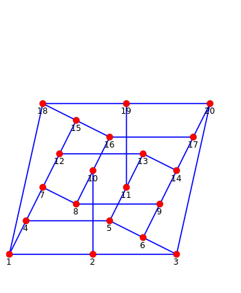
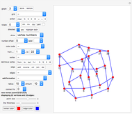
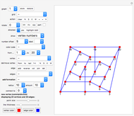
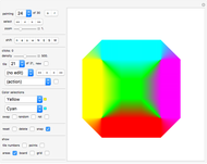
Graph 1 shows a nice embedding of a cubic graph with six crossings found by Ed Pegg Jr.
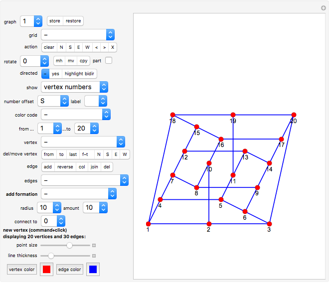
Graphs 2 to 6 show various graphs where you can try to find a nice representation similar to the one given in graph 1. The graph should be very symmetric or with minimum crossings (or both).
Graph 7 is a special default setup (with vertices arranged in two straight lines) that you can use to develop your own graphs. You can create similar setups with the special formation "rectangle".
Permanent Citation
"Constructing and Manipulating Graphs"
http://demonstrations.wolfram.com/ConstructingAndManipulatingGraphs/
Wolfram Demonstrations Project
Published: January 8 2009
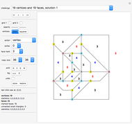 Alternating Planar Graphs
Karl Scherer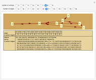 Enumerating the Directed Graphs
Seth J. Chandler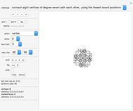 Graph Puzzles
Karl Scherer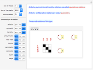 Relations and Graphs
Jaime Rangel-Mondragon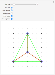 Sphere-of-Influence Graphs
Edray Herber Goins and Talitha M. Washington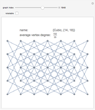 Average Vertex Degree of Connected Graphs
John Cicilio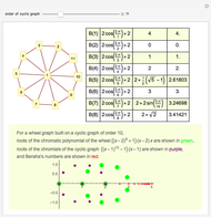 Beraha's Conjecture, Wheels, and Cyclic Graphs
Jacqueline Zizi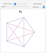 Coloring Cycle Decompositions in Complete Graphs on a Prime Number of Vertices
Michael Morrison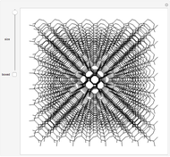 Tridimensional Trivalent Graph
Raymond Aschheim De Bruijn Graph Arcs
Michael Schreiber
-
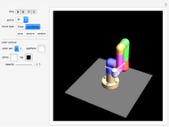
 Polyhedral Playground
Karl Scherer -
 Tiling Constructor, Tile-Dragging Variant
Karl Scherer -
 The Catenax Puzzle
Karl Scherer -
 Angel Puzzle
Karl Scherer -
 Constructing and Manipulating Graphs
Karl Scherer -
 3D Construction Set
Karl Scherer -
 Blended Quadrilaterals
Karl Scherer -
 Rotating Polyhedra in Space
Karl Scherer -
 The Misdirection Game
Karl Scherer -
 Tensegrity
Karl Scherer -
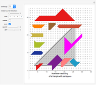 Nowhere-Neat Tilings
Karl Scherer -
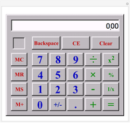 Pocket Calculator
Karl Scherer -
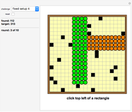 Area Puzzle
Karl Scherer -
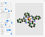 Molecule Construction Set
Karl Scherer -
 The Ray Puzzle
Karl Scherer -
 Animated Model of an Industrial Robot Arm
Karl Scherer -
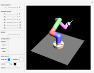 Model of an Industrial Robot Arm
Karl Scherer -
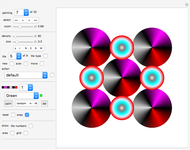 Color-Blended Circular Tiles
Karl Scherer -
 Rep-Tiles
Karl Scherer -
 Armed Balloons Puzzle
Karl Scherer