Phasor Diagram for Series RLC Circuits
Initializing live version

Requires a Wolfram Notebook System
Interact on desktop, mobile and cloud with the free Wolfram Player or other Wolfram Language products.
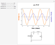
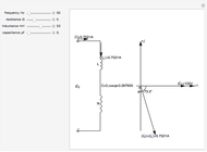
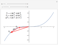
This Demonstration shows a phasor diagram in an AC series RLC circuit. The circuit consists of a resistor with resistance  , an inductor with inductance
  , and a capacitor with capacitance
  . The current in an RLC series circuit is determined by the differential equation
Contributed by: Anping Zeng (July 2011)
(Sichuan Chemical Technical College)
Open content licensed under CC BY-NC-SA
Snapshots
Details
Snapshot 1:  ,
,  ,
,  leads the current
Snapshot 2:  ,
,  ,
,  leads the current
Snapshot 3:  or
or  ,
,  , resonance
For more information, see Phasor Diagrams.
Permanent Citation


