Improving Power Factors in an AC Circuit


Requires a Wolfram Notebook System
Interact on desktop, mobile and cloud with the free Wolfram Player or other Wolfram Language products.
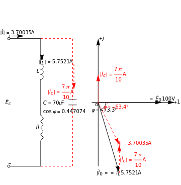
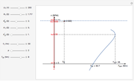
This Demonstration shows how to improve the power factor in an AC circuit. A power factor correction for a given load voltage and current can reduce operating costs. As described in Details, the key formulas are  ,
,  ,
,  ,
,  , where
  is the AC emf driving the circuit. The angular frequency
  is related to the frequency
  in hertz (Hz) by
  . In this Demonstration, the amplitude
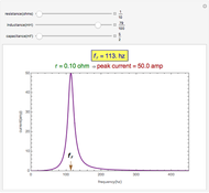
  is set at 100 volts (V). You can vary the frequency
  in Hz, the resistance
  in ohms (
 ), the inductance
  in millihenries (mH), and the capacitance
  in microfarads (
 F). The phase of
  lags that of
  by
by  . The phase of
  lags that of
  by
by  , where

 ,
,  .
.

Contributed by: Anping Zeng (August 2011)
(Sichuan Chemical Technical College)
Open content licensed under CC BY-NC-SA
Snapshots


Details

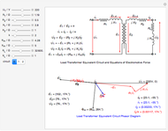
(a) The original inductive load. (b) The inductive load with improved power factor correction.

(c) The lower triangle of power factor correction; this shows the capacitance value needed to change the pf angle from  to
to  . (d) The affect of the capacitor on the total current; when paralleling the capacitance
  , the power factor is improved;
  .
.
Permanent Citation
 Frequency Response of an LCR Circuit
Contributed by: Kallol Das (St. Aloysius College, Jabalpur, India)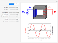 AC Transformers
S. M. Blinder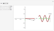 Phasor Model for RC Filter Electronic Circuit
Michael R. Braunstein (Central Washington University)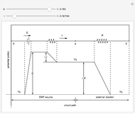 Potential Differences in a Circuit with an EMF Source
Enrique Zeleny Simplest Chaotic Circuit
Bharathwaj Muthuswamy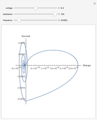 Chaotic Oscillation Circuit
Michael Schreiber Magnetic Circuits
Stephen Wilkerson (United States Military Academy West Point) Open Circuit Voltage Coupled into a Semi-Infinite Transmission Line by an Exponential, Plane Waveform
Michael J. Walker Balanced T-Coil Parameters
Allen Hollister Parallel Plate Capacitors and RC Circuits
Greggory Rothmeier
-
 Torque and Speed Characteristics of Separately Powered DC Motors
Anping Zeng -
 Circuit Phasor Diagram for Transformers
Anping Zeng -
 Characteristics of Three-Phase Asynchronous Motors
Anping Zeng -
 Joule's Experiment and the First Law of Thermodynamics
Anping Zeng -
 Moving Wave Analysis
Anping Zeng -
 Improving Power Factors in an AC Circuit
Anping Zeng -
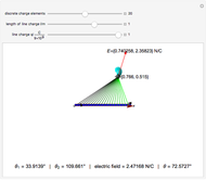 Electric Field of a Line of Charge
Anping Zeng -
 Phasor Diagram for Series RLC Circuits
Anping Zeng -
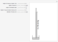 Torricelli's Experiment
Anping Zeng -
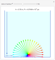 Fluid Pressure
Anping Zeng -
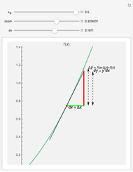 Geometric Difference between a Finite Difference and a Differential
Anping Zeng -
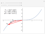 Displacement along a Curve
Anping Zeng