Electromagnetic Wave Incident on a Perfect Conductor


Requires a Wolfram Notebook System
Interact on desktop, mobile and cloud with the free Wolfram Player or other Wolfram Language products.
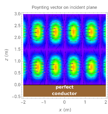
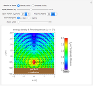
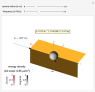
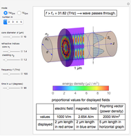
This Demonstration shows an electromagnetic wave incident on a perfect conductor calculates the corresponding Poynting vector. The incident wave is assumed to be linearly polarized in the horizontal or vertical direction (with respect to the electric field). The resulting Poynting vector pattern is shown on the incident  -
- plane. In all cases, the amplitude of the incident electric field is set to
  , which corresponds to
  or
or  in power density.

Contributed by: Y. Shibuya (October 2012)
Open content licensed under CC BY-NC-SA
Snapshots


Details
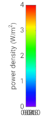
Snapshot 1: Poynting vector plot for vertically polarized incident wave at angle 
Snapshot 2: Poynting vector plot for incident wave of (same for horizontal or vertical waves)
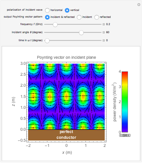
Snapshot 3: Poynting vector plot for reflected wave for incident wave of (same for horizontal or vertical waves)
For the horizontally-polarized electromagnetic wave propagating along the axis, the electric field is given by  , while for the vertically-polarized wave,
  . Here,
  is the propagation factor. In both cases, the corresponding magnetic field is given by
  , where
  is the propagation direction, and
  is the wave impedance.
Similarly, the fields for the incident angle  can be determined for both incident reflected waves as
  . Then the resultant fields
  and
and  can be obtained by superposition. The Poynting vector can be calculated accordingly.
The Poynting vector pattern of the incident wave (or reflected wave) is the same whether the polarization is horizontal or vertical. However, the superposed pattern is different because the reflected wave's phase depends on the polarization.
The Poynting vector's intensity and direction are shown by colors and arrows in the output pattern. The intensity increases as approaches 90°, and the average direction is always toward the positive direction.
Reference
[1] D. K. Cheng, Field and Wave Electromagnetics, 2nd ed., Reading, MA: Addison-Wesley, 1989.
Permanent Citation
 Electromagnetic Wave from Dipole over a Perfect Conductor
Y. Shibuya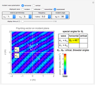 Electromagnetic Wave Incident on a Dielectric Boundary
Y. Shibuya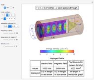 Electromagnetic Waves in a Cylindrical Waveguide
Y. Shibuya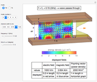 Electromagnetic Waves in a Parallel-Plate Waveguide
Y. Shibuya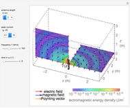 Electromagnetic Waves from a Linear Antenna
Y. Shibuya Electromagnetic Fields in Wireless Power Transmission
Y. Shibuya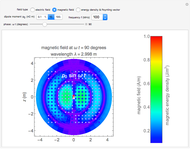 Electromagnetic Fields For Hertzian Dipoles
Y. Shibuya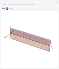 Electromagnetic Wave
Enrique Zeleny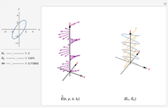 Polarization of an Electromagnetic Wave
Luis Jonathan Cervantes Rosas Propagation of a Plane Electromagnetic Wave
Alan Fafard
-
 Skin Effects in Straight Wires
Y. Shibuya -
 Leakage Inductance in a Transformer
Y. Shibuya -
 Electromagnetic Wave Scattering by Conducting Sphere
Y. Shibuya -
 Cylindrical Cavity Resonator
Y. Shibuya -
 Electric Fields for Pairs of Cylinders or Spheres
Y. Shibuya -
Electromagnetic Fields in Wireless Power Transmission
Y. Shibuya -
 Wireless Power Transmission
Y. Shibuya -
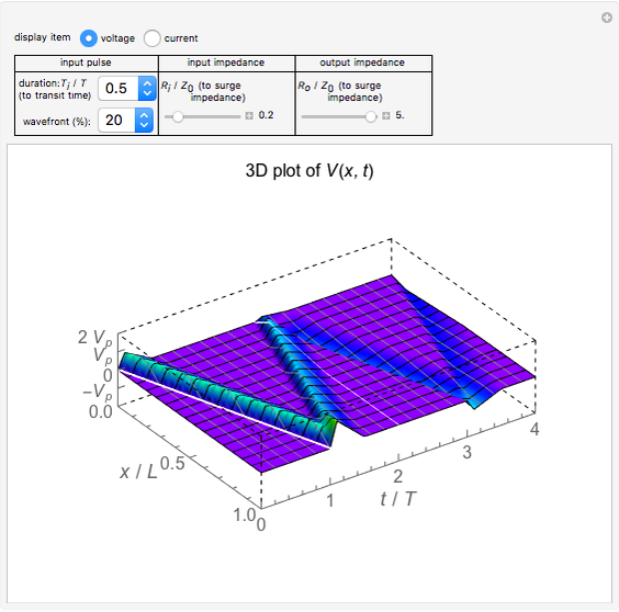 Surge Propagation in a Transmission Line
Y. Shibuya -
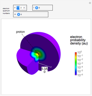 Electron Probability Distribution for the Hydrogen Atom
Y. Shibuya -
 Magnetic Shielding Effect of a Spherical Shell
Y. Shibuya -
Electromagnetic Waves from a Linear Antenna
Y. Shibuya -
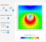 Current-Carrying Wire in Uniform Magnetic Field
Y. Shibuya -
Electromagnetic Wave Incident on a Dielectric Boundary
Y. Shibuya -
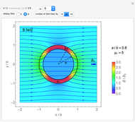
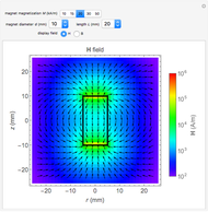 Magnetic Field and Magnetic Induction in a Cylindrical Bar Magnet
Y. Shibuya -
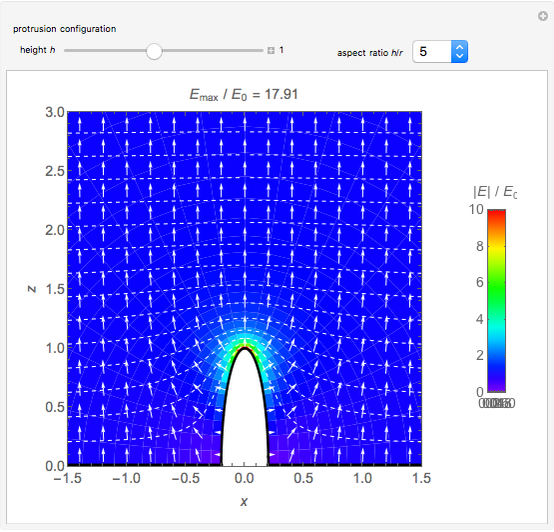 Spheroidal Protrusion in a Uniform Electric Field
Y. Shibuya -
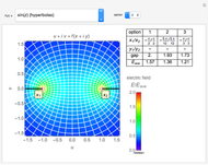 Electrostatic Fields Using Conformal Mapping
Y. Shibuya -
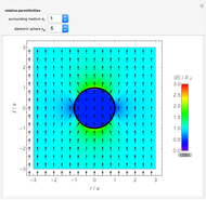 Dielectric Sphere in a Uniform Electric Field
Y. Shibuya -
 Electromagnetic Waves in Optical Fibers
Y. Shibuya -
Electromagnetic Waves in a Cylindrical Waveguide
Y. Shibuya -
Electromagnetic Waves in a Parallel-Plate Waveguide
Y. Shibuya