Dual Slope Analog-to-Digital Converter


Requires a Wolfram Notebook System
Interact on desktop, mobile and cloud with the free Wolfram Player or other Wolfram Language products.
Analog-to-digital conversion has been increasingly important since the dawn of the digital era. There are actually dozens of different conversion techniques employed by electrical engineers, each with their own advantages and disadvantages.
[more]


Contributed by: Roy Rinberg (May 2014)
Open content licensed under CC BY-NC-SA
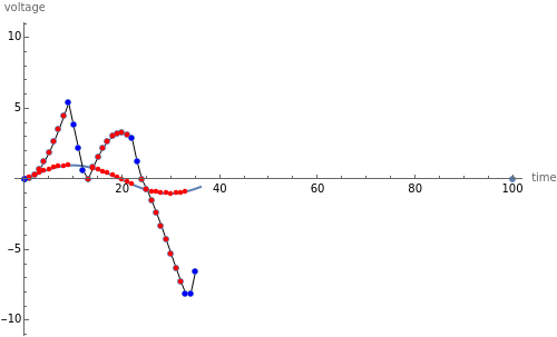
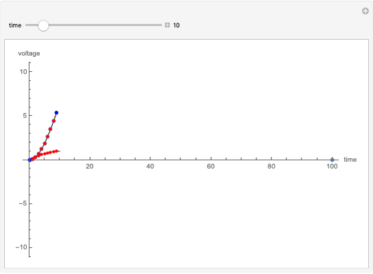
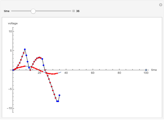
Snapshots


Details
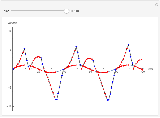
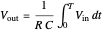
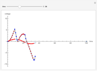
Dual slope is a spin-off of the simplest types of analog-to-digital conversion, as shown in the Demonstration "Analog-to-Digital Conversion Algorithm with a Single Slope". Single slope operates by using a capacitor to create a linear voltage ramp to compare the actual signal to, and then recording the time it takes the linear ramp to reach the signal (as it is a linear voltage ramp, the time it takes is linearly proportional to the voltage itself). The problem with single slope is that it uses a capacitor as its method of integration; this requires a very consistent capacitor that does not accumulate errors over time (drift), which is not only very difficult to do, but very expensive. Interestingly enough, dual slope fixes this problem by having the capacitors do two integrations, one after another rather than just one. First the integrator integrates the signal, then it integrates a constant voltage; because these integrations happen directly after one another, you can set them to be the same  (the first one goes from 0 V to
  and the second goes from
  to 0 V) so you get
  . Because these integrations happen thousands of times per second, you can assume that the resistor and capacitor remain constant during one pair of integrations, so you can cancel the
  values on both sides. This makes dual slope very reliable with high fidelity, as it no longer depends very much on the fidelity of the capacitor (typically a very finicky component).
Reference
[1] P. Horowitz and W. Hill, The Art of Electronics, Cambridge: Cambridge University Press, 1998.
Permanent Citation
 PR4 Coding of a Magnetic Hard Drive
Charles Masenas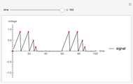 Analog-to-Digital Conversion Algorithm with a Single Slope
Roy Rinberg Estimating a Centered Ornstein-Uhlenbeck Process under Measurement Errors
Didier A. Girard Phasor and Temporal Diagrams in Electrical Power-System Fault Analysis
Daniel Motter Digital Filters with Windowed Sinc Finite Impulse Response
Dana Tremblay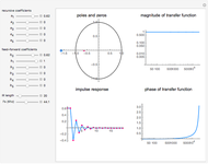 Digital IIR Filter Design Showing Poles and Zeros
Hans Anderson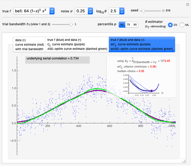 Nonparametric Curve Estimation by Kernel Smoothers under Correlated Errors
Didier A. Girard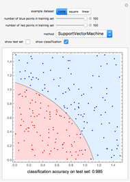 Comparison of Different Methods for the Binary Classification of Points in the Plane
Frank Brechtefeld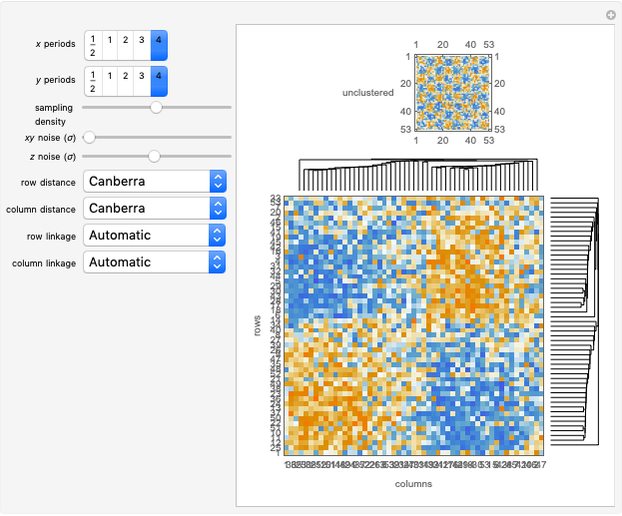 Hierarchical Clustering and Heat Maps in Mathematica
Michael A Gibson Automatically Selecting Histogram Bins
Brett Champion