Radio Propagation and Multipath with Diversity Antennas


Requires a Wolfram Notebook System
Interact on desktop, mobile and cloud with the free Wolfram Player or other Wolfram Language products.
This Demonstration shows the propagation between two antennas of heights  and
and  above ground and the effect of multipath radiation from the ground bounce. The result is multiple nulls or actual fades. It also show the result of adding a diversity antenna of height
  above the height of antenna 1. It includes the effects of the reflection coefficient from the ground as a function of the angle of incidence and the dielectric constant of earth.
Contributed by: Allen Hollister (October 2009)
Open content licensed under CC BY-NC-SA
Snapshots


Details
Picture three antennas; a transmitting antenna of height (above ground), a receiving antenna of height (above ground), and a second receiving antenna (called the diversity antenna) of height above . A signal being transmitted from transmitter to receiver has a direct path and an indirect path. The indirect path is the path taken when the signal goes from the transmitter, reflects off the ground, and bounces back up to the receiver antenna. This second path is sometimes referred to as a multipath and the general problem is called the multipath problem. The result of this second indirect path is the summation of the two received signals. The indirect path is a longer path so its phase relative to the direct path changes as the distance between the antennas change. If the phase happens to be in phase, it is possible to double the signal strength at the receiver, but if the phase is 180 degrees out of phase, complete signal cancellation can occur, resulting in a signal fade (loss of signal) at that particular distance. The diversity antenna is designed to prevent this problem because it is at a different distance from the transmitter antenna than the first receiver antenna. This means the phase received at that antenna will be different from that at the original receiver antenna. Hopefully, it will be an in-phase rather than an out-of-phase signal. The receiver chooses which antenna has the stronger signal and thereby is more immune to complete fades caused by multipath.
The actual amount of indirect path signal received is dependent on a couple of things. Specifically it is dependent on the reflectivity of the ground modeled by the reflection coefficient of ground. This is a complex number that is a function of the dielectric coefficient of the Earth, the conductivity of Earth (both of these change for different kinds of Earths), the wavelength, and the antenna polarization. At the frequencies of interest and with normal kinds of Earths, the conductivity is a third-order effect and for simplicity conductivity is equal to zero for this Demonstration. In general, "poor" Earth has a dielectric constant of 4, while "good" Earth has a dielectric constant of 30. The dielectric constant for air is 1. The actual reflection coefficient can range from  to
to  . For very small angles (the antenna height is short with respect to the distance between antennas), it approaches . Many people just assume that the reflection coefficient is , but this is not a good assumption for the short-range microwave communications systems in use today.
The second thing that can cause attenuation of the indirect signal relative to the direct path distance is the fact that the indirect path is simply longer. The standard path loss equation tells us that the greater the distance, the less the signal. For example, assume that the distance between the antennas is 1 meter while they are 10 meters above ground. The direct path would be 1 meter; the indirect path would be about 20 meters. The result would be a much stronger signal from the direct path. However once again, as the distance between the antennas increase, the direct path distance approaches the indirect path distance and this effect goes away.
The result of these two effects is that the nulls and fades actually get worse with distance.
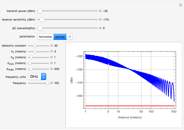
There is also the effect of antenna polarization. For horizontal polarization (where the electric field is horizontal with respect to the ground), the reflection coefficient is always negative. For vertical polarization, the reflection coefficient for large angles begins at , goes through zero as the angle decreases, and approaches as the angle becomes very shallow. The angle at which the reflection coefficient is zero is referred to as the Brewster angle. All of this is modeled in this Demonstration.
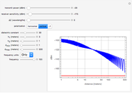
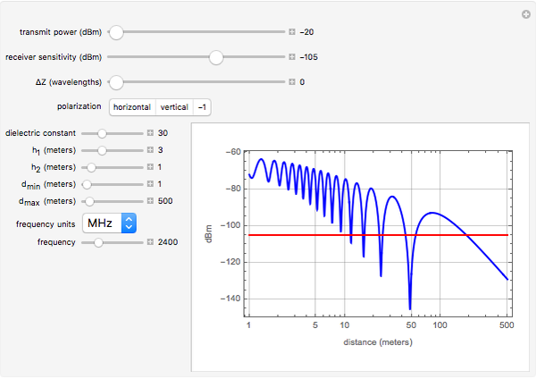
Specifically, the Demonstration shows a plot of the received signal strength as a function of the distance between the two antennas. The slider labeled "transmit power" lets you select the transmitter power in dBm.
The slider labeled "receiver sensitivity" lets you select the sensitivity of your receiver in dBm. This is shown by the red line on the graph. Anytime the graph of received power (the blue trace) is less than this (blue goes below red), the receiver will lose signal and a fade will occur.
The slider labeled sets the height of the diversity antenna above that of the height of the receiver antenna. The height is in wavelengths, not meters!
The button labeled "polarization" lets you select horizontal or vertical polarization. It also lets you select a reflection coefficient of , which is the limiting factor as  approaches infinity for either horizontal or vertical polarization.
The sliders and select the height of the receiver and transmitter antennas in meters.
The sliders  and
and  let you zoom in on any particular distance you choose.
Finally, you can set the frequency of interest with the dropdown menu "frequency units", where you can select either MHz or GHz and the slider "frequency" that sets the actual frequency. Thus if "frequency units" is set to MHz, and "frequency" is set to 2400, the frequency used is 2400 MHz.
The last of the three snapshots shows what happens when the dielectric constant is set to 1. Because 1 is the dielectric constant of free space, this effectively removes ground as a reflector. Hence there is no multipath signal. The result is a free space pure path-loss attenuation with distance—no nulls.
While this problem was set up to model the ground bounce multipath, there is no reason not to use it to model the reflection from walls or ceilings. Just be sure you get the antenna polarization correct and use an appropriate value for the dielectric constant for the wall in question.
If you have something strange like a wall, ceiling, or floor made of metal, then the assumption that the reflection coefficient is dominated by the real part (dielectric constant only) is not valid. You need to add in the imaginary part that contains the conductivity of the material. The equations for this are long and they tend to dramatically slow down Mathematica (it requires several seconds to complete each calculation any time a slider is moved) and would not have made a good Demonstration. However, the equations to model this are available on my website in a paper (PDF file) called RadioPropagation (See links above) in case you need this additional accuracy. This paper also gives the derivation of all of the equations used in this Demonstration.
References
[1] A. Hollister, Wideband Amplifier Design, Raleigh, NC: SciTech Publishing, 2007.
[2] Besser Associates Class, Wideband/HF Amplifier Design Techniques.
Permanent Citation
 Energy and Power of Signals
Daniel de Souza Carvalho Complex and Real Planes of Discrete Fourier Transforms
Daniel de Souza Carvalho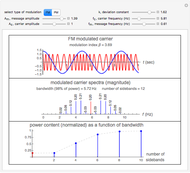 Power Content of Frequency Modulation and Phase Modulation
Nasser M. Abbasi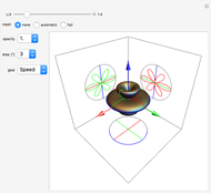 Dipole Antenna Radiation Pattern
Nikolitsa Yannopoulou and Petros Zimourtopoulos (Antennas Research Group, Xanthi, Thrace, Hellas, EU) Beat Frequency of Sound Waves
Christopher Engberg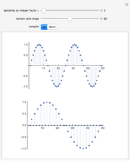 Sampling a Digital Signal
Siva Perla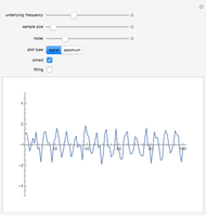 Frequency Spectrum of a Noisy Signal
Jon McLoone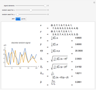 Correlation and Covariance of Random Discrete Signals
Daniel de Souza Carvalho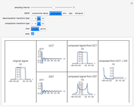 Discrete Fourier Sine and Cosine Transforms
Daniel de Souza Carvalho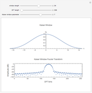 Kaiser Window Transform
Jeff Bryant