Interactions between Textured Glue Particles and a Ball Based on Idealized Dynamics

Requires a Wolfram Notebook System
Interact on desktop, mobile and cloud with the free Wolfram Player or other Wolfram Language products.
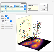
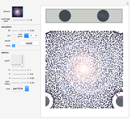
A ball with mass  is placed within a 3D glue layer that is represented by a collection of glue particles of various colors. Every glue particle is affected by the presence of the ball and therefore moves to a new position due to the ball's location. The force between the ball and any glue particle is determined by both the displacement and color of that particle. The ball is initially static but it begins to move due to the nonzero resultant force acting on it. As we will not consider the case when the ball is forced out of the glue layer, the movement of the ball's center is restricted within the middle section of the glue layer.
Contributed by: Yiyang Li (January 2012)
Open content licensed under CC BY-NC-SA
Snapshots
Details
This Demonstration is based on idealized dynamics because it ignores the viscosity coefficients and temperature, which are of central concern to real glue. Instead, the movement of any glue particle simply obeys a geometrical rule. This has the advantage that we no longer need to consider the interaction among different glue particles.
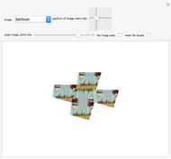
We choose a picture as a color source and extract color data from it. Then we apply the color data to a collection of random glue particles distributed within a cuboid region  . More specifically, first we partition the source picture into several subimages, then we calculate the mean color of each subimage, and finally we apply the mean colors to the random glue particles in order. This gives a layer representative of the source picture, as long as the subimage's pixel value is small enough. The size of the cuboid region
  runs from 1 to
  , 1 to
  , and 1 to
  in the
  ,
,  , and
, and  directions, where
  ,
,  , and
, and  are determined by the magnitude of both the source picture and the subimage. It may take a long time to render with a small subimage setting because there can be a huge amount of particles with various colors, so do not set the subimage's pixel value to less than 10 in the source code unless you are using a powerful computer. You can use a different picture as a color source.
Glue Particle Dynamics
Here is the geometrical rule governing the movement of glue particles: if the ball's center is located at position  and a glue particle
  , which is initially located at position
  , moves to a new location
  under the influence of
  , then
(1)  ,
,
where  is an adjustable parameter. We also apply a periodic framework setting in this Demonstration. So, if the ball
  leaves the cuboid region
  from its left boundary, it then enters from the right boundary at the same time. This periodic setting requires us to consider the influences of the eight corresponding balls
  located in the eight surrounding congruent regions
  that enclose
  ;
;  forms a bigger cuboid region that looks like
 .
.
(2)  .
.
As a result, the glue particle  's new location
  should be modified to
(3)  .
.
However, as the collection of random glue particles normally contains several thousand particles and equation (3) greatly increases the calculation, we applied several simplified versions of equation (3) in the source code due to ball  's position within the cuboid region
  , so that the summation in equation (3) contains only one, two, or four items.
(4) 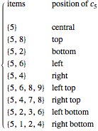
In this way, we slightly sacrifice precision but gain remarkably on efficiency. Please refer to the program for more details about how to determine the position. Also, notice that  may belong to another
  region.
Glue-Ball Interaction
Under the influence of the balls, a glue particle  will move from its initial position
  to its new position
  . If the color of this particle is described as
  where
where  , then the force
  between particle
  and the ball
  is defined as
(5)  ,
,
where  is an adjustable parameter,
  is treated as a vector, and the vector
  refers to particle
  's displacement caused by the existence of ball
  (see equation (1), for example). It is obvious that
  points to the sphere center of
  , thus the ball
  will only have translational motion. According to the periodic setting, we only need to calculate the resultant force acting on the ball
  alone and track its motion step by step, since the locations of the other balls can be deduced from equation (2). (In fact, if we want to directly calculate the locations of all
  , a 3×3
  region is still insufficient.) During simulation, whenever
  leaves the
  region, we use the periodic setting to reset its position within
  . In this way, it is always ensured that
  and we only need to focus on the calculation regarding
  alone throughout the whole simulation.
A cutoff setting for the resultant force calculation is also adopted in order to improve efficiency. That is, only those particles in the vicinity of ball  will be considered for the resultant force acting on
  , because in this Demonstration it is ensured that
  if
if  is not in the vicinity of
  ; thus, the force contribution of other particles can actually be ignored. More specifically, a glue particle
  will be considered for the force calculation if
(6)  .
.
As all glue particles are initially randomly distributed, a test like equation (6) can be somewhat time consuming, so we also use a "floating filter" approximation to accelerate data processing; please refer to the source code for details. Based on the cutoff setting, the force  can be simply calculated as
(7) 
for any particle  in the vicinity of
  , because
  's final position
  is determined in advance in our source code.
When the ball  is located at the boundary of region
  , parts of the ball will belong to other
  regions, and the direct adoption of equation (7) requires us to consider particles belonging to other
  regions as well. For example, if the position is at the bottom left, the force calculation involves particles belonging to region
  as well as regions
  ,
,  , and
, and  . But it will be much better if only the particles belonging to
  are taken into consideration, since the number of particles in
  can be large. This concern can be met by adopting the periodic setting—we can investigate the forces acting on the
  ,
,  , and
, and  balls' corresponding parts instead, which now belong to
  . In practice, we first need to take in the
  region where those particles are interacting with
  and
and  , then combine them in the correct order into a partitioned matrix. If we denote
  as the matrix containing those particles' initial coordinates and
  as the matrix containing those particles' final coordinates, then
  provides all the data required by equation (7). The resultant force (represented as a red arrow) only exerts influence over the balls' motion, as all the glue particles' motion is governed by idealized (or fake) dynamics.
Ball Lighting Specification
Like the cutoff setting adopted in equation (6), we define  and set those glue particles satisfying
  as spotlight sources that aim at
  with different half-angles, so that the light spots on the ball surface will have the same size. When the ball
  is located at the boundaries of the region
  , similar operation as mentioned above is applied.
Possible Issue
If the ball lighting appears inverted when crossing  's boundaries, you need to search within the source code for (*Reverse@*)VLPC and change them to Reverse@VLPC (this occurs three times). This problem appears to depend on the operating system: on Windows XP, VLPC yields the correct result, but on Windows 7, we need to use command Reverse to modify VLPC.
Ball Radius Determination
As both the glue particle dynamics and the glue-ball interaction are idealized, the ball's size must be determined with caution so the Demonstration can appear valid. We mainly use the coordinates of those spotlight sources for radius calculation at every step, so the ball's size may vary at every step. (Actually, radius varies little and the naked eye can hardly notice the change.)
2D Force Field Calculation
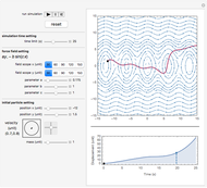
In order to better understand the ball's motion, we take about 1000 sample points evenly distributed within the middle section of the glue layer and calculate the corresponding force vectors (ignoring the  direction). This process may take several minutes to complete and it is not for real-time simulation, so we simply import the calculated result as an image.
A few videos of this Demonstration can be downloaded from my personal page.
Permanent Citation


