Joint Space and Tooling Space for Robot Motion Control

Requires a Wolfram Notebook System
Interact on desktop, mobile and cloud with the free Wolfram Player or other Wolfram Language products.
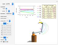
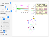
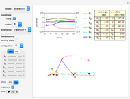
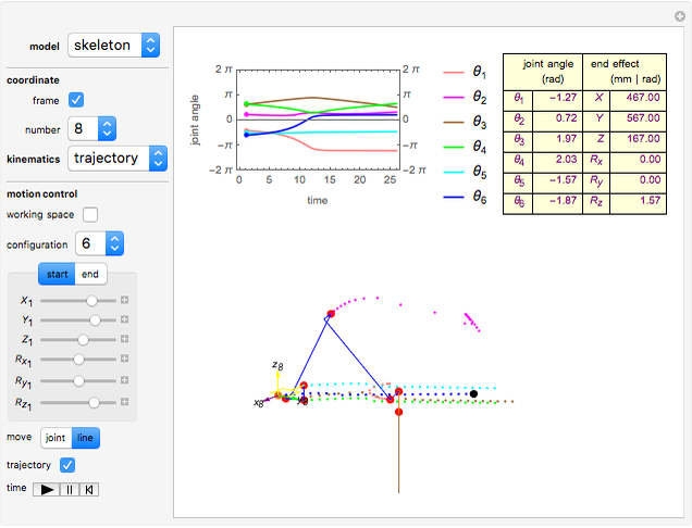
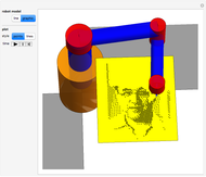
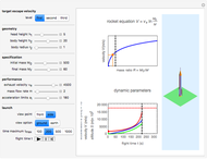
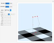
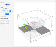
This Demonstration shows the move-joint and move-line methods that are used to control the manipulator trajectory of an industrial robot.
[more]
Contributed by: Frederick Wu (September 2016)
Open content licensed under CC BY-NC-SA
Snapshots


Details
References
[1] J. Denavit and R. S. Hartenberg, “A Kinematic Notation for Lower-Pair Mechanisms Based on Matrices,” Journal of Applied Mechanics, 22(2), 1955 pp. 215–221.
[2] H. Lipkin, “A Note on Denavit–Hartenberg Notation in Robotics,” in ASME 2005 International Design Engineering Technical Conferences and Computers and Information in Engineering Conference, Long Beach, CA, 2005. New York: American Society of Mechanical Engineers, 2005. doi:10.1115/DETC2005-85460.
[3] J. J. Craig, Introduction to Robotics: Mechanics and Control, 3rd ed., Upper Saddle River, NJ: Pearson/Prentice Hall, 2005 pp. 62–82.
[4] B. Siciliano and O. Khatib, eds., Springer Handbook of Robotics, Berlin: Springer–Verlag, 2008.
[5] B. Siciliano, L. Sciavicco, L. Villani and G. Oriolo, Robotics: Modelling, Planning and Control, London: Springer, 2009.
[6] D. L. Pieper, “The Kinematics of Manipulators under Computer Control,” (Stanford Artificial Intelligence Laboratory Memo, No. AI-72), Ph.D. dissertation, Computer Science Department, School of Humanities and Sciences, Stanford University, CA, 1968. www.dtic.mil/cgi-bin/GetTRDoc?AD=AD0680036.
[7] M. Raghavan and B. Roth, “Kinematic Analysis of the 6R Manipulator of General Geometry,” in Proceedings of the Fifth International Symposium on Robotics Research (H. Miura, ed.), Cambridge, MA: MIT Press, 1990 pp. 263–269. dl.acm.org/citation.cfm?id=112715&CFID=542850644&CFTOKEN=11490130.
[8] D. Manocha and J. F. Canny, “Efficient Inverse Kinematics for General 6R Manipulators,” IEEE Transactions on Robotics and Automation, 10(5), 1994 pp. 648–657. doi:10.1109/70.326569.
[9] R. N. Jazar, Theory of Applied Robotics: Kinematics Dynamics and Control, 2nd ed., New York: Springer, 2010 pp. 341–363.
[10] UR10/CB3 User Manual, Version 3.1, Denmark Odense: Universal Robots A/S, 2015. (Aug 26, 2016) www.universal-robots.com/media/8755/ur10_user_manual _da _global.pdf.
[11] The URScript Programming Language, Version 3.1, Denmark Odense: Universal Robots A/S, 2015. (Aug 26, 2016) www.sysaxes.com/manuels/scriptmanual_en_ 3.1.pdf.
Permanent Citation
"Joint Space and Tooling Space for Robot Motion Control"
http://demonstrations.wolfram.com/JointSpaceAndToolingSpaceForRobotMotionControl/
Wolfram Demonstrations Project
Published: September 13 2016
 Fractal Robot Arm
Sándor Kabai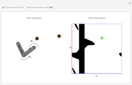 Robot Motion with Obstacles
Aaron T. Becker and Haoran Zhao Forward Kinematics of Humanoid Robots
Frederick Wu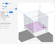 Kinematics of a Redundant Anthropomorphic Arm with Seven Degrees of Freedom
Frederick Wu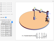 Common Robot Arm Configurations
Mohammad Sultan and Aaron T. Becker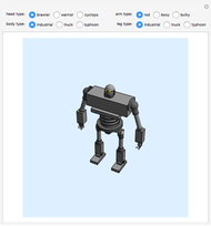 Robot Builder
Frank Liao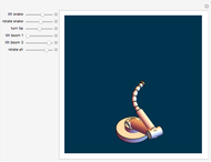 Snake-Arm Robot
Sándor Kabai Inverse Kinematics in Redundant Robot Manipulator
André Carvalho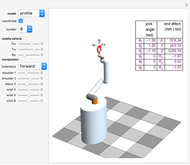 Mobile Robot with Single Manipulator
Frederick Wu Inverse Kinematics for a Robot Manipulator with Six Degrees of Freedom
Frederick Wu
-
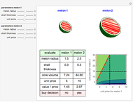 Buying Watermelons Intelligently
Frederick Wu -
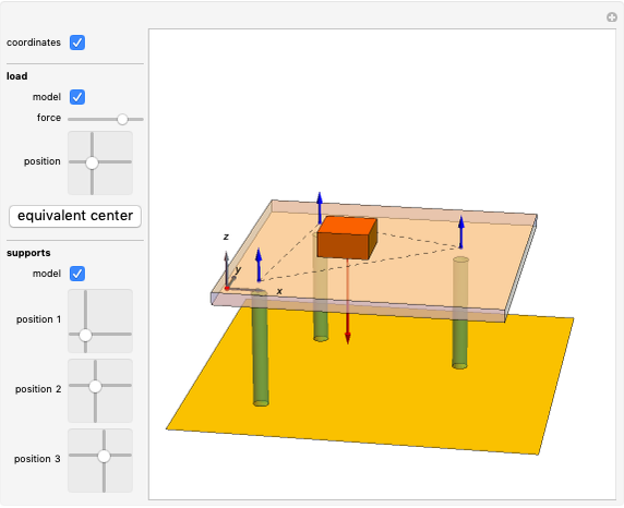 Static Equilibrium for a Plate with Support at Three Points
Frederick Wu -
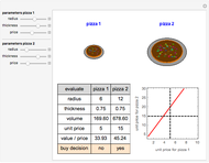 Evaluate Hot Pizza
Frederick Wu -
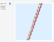 Rubik's Snake Puzzle
Frederick Wu -
Mobile Robot with Single Manipulator
Frederick Wu -
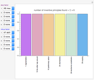 Multiple Input Parameters for TRIZ Matrix Application
Frederick Wu -
 Joint Space and Tooling Space for Robot Motion Control
Frederick Wu -
 Trajectory Planning of Robot for Painting Art
Frederick Wu -
Inverse Kinematics for a Robot Manipulator with Six Degrees of Freedom
Frederick Wu -
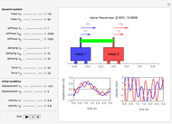 Spring-Mass-Damping System with Two Degrees of Freedom
Frederick Wu -
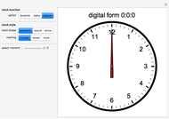 When Do the Three Hands of an Analog Clock Overlap?
Frederick Wu -
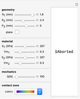 Hertzian Contact Stress
Frederick Wu -
 Launching a Rocket
Frederick Wu -
 Kinematics of Biped Legs for Humanoid Robots
Frederick Wu -
 Intersection of a Convex Polyhedron and a Plane
Frederick Wu -
Kinematics of a Redundant Anthropomorphic Arm with Seven Degrees of Freedom
Frederick Wu -
 Forward and Inverse Kinematics of the SCARA Robot
Frederick Wu -
Forward Kinematics of Humanoid Robots
Frederick Wu -
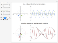 Complex Addition of Harmonic Motions and the Phenomenon of Beats
Frederick Wu -
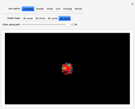 Shortening the 29th Olympic Torch Tour
Frederick Wu