Induction in a Coil by a Gaussian Magnetic Field

Requires a Wolfram Notebook System
Interact on desktop, mobile and cloud with the free Wolfram Player or other Wolfram Language products.
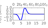
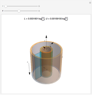
According to Faraday's law, a varying magnetic field induces a current and voltage in a coil. This Demonstration shows graphically the effect of a magnetic field on a circular coil. Assuming a temporal near-field, the magnetic field is assumed to be uniformly distributed in space. Since the coil has an inductance, the current and voltage shown on an oscilloscope are determined by the circuit configuration. The current and voltage waveforms can be calculated for four different circuits: open circuit, usual oscilloscope impedance ( ), cable's matching impedance (
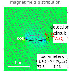
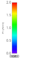
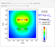
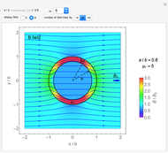
 ), and shorted condition. The magnetic field waveform is either a Gaussian pulse or one of its derivatives up to third order. The spatial directions can be varied. You can change the coil configuration (radius, winding cross sectional diameter, and number of turns). The sideways view of the magnetic field pattern determined by the coil current, as a function of time, is displayed using colored contours and arrows.
Contributed by: Y. Shibuya (November 2012)
Open content licensed under CC BY-NC-SA
Snapshots
Details
Snapshot 1: a shorted five-turn coil is placed upright beside a third-derivative Gaussian pulse field
Snapshot 2: a five-turn coil is connected to a  detection circuit for the field of a third-derivative Gaussian
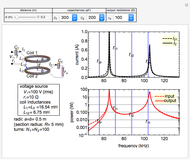
Snapshot 3: an increased-turn (30) coil resonates with the capacitor of a  detection circuit
The Gaussian function and its derivatives (i.e.
  ,
,  , ⋯) are often used to represent temporal changes. Assuming the applied magnetic field
  to be one of those waveforms, the transient current and voltage induced in a circular coil are analyzed. In all of those cases, the maximum is normalized to 1 A/m, and the origin is shifted to
  , for example, as
  . According to Faraday's law, the electromotive force (EMF) in a circular coil is given by
 ,
,  and
and  being the radius and number of turns and
  being the angle between field and coil axis. Assuming a circular section of coil of diameter
  , the coil's inductance is approximated by
  . Then the transfer function of current or voltage in the detection circuit can be obtained. Let
  be the indicial response of the system; the actual response can be calculated by Duhamel's integral
  . Here,
  can be obtained by a Laplace transform.
The coil current produces a magnetic field that is superimposed on the original field. The additional magnetic field from the ring current can be calculated in terms of Bessel functions. The magnetic field pattern is readily obtained as a function of time.
Among the four circuits considered, the detected current increases in this order: open circuit,  ,
,  , and shorted conditions in general. The detected voltages vary in the opposite order. However, in the detection circuit of
  , a large current and voltage can occur due to resonance between the coil inductance and the capacitor in the detection circuit, as shown in Snapshot 3.
References
[1] J. D. Jackson, Classical Electrodynamics, New York: John Wiley & Sons, 1998.
[2] A. L. Shenkman, Transient Analysis of Electric Power Circuit Handbook, New York: Springer, 2005.
Permanent Citation
