Drilling a Pentagonal Hole


Requires a Wolfram Notebook System
Interact on desktop, mobile and cloud with the free Wolfram Player or other Wolfram Language products.
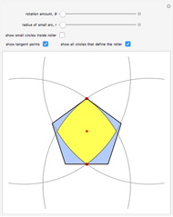
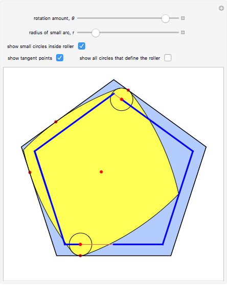
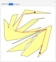
The construction shown lets you turn circular motion into pentagonal motion and so construct a drill that drills pentagonal holes. The roller—the yellow shape that rotates within the large pentagon—consists of six circular arcs. As it rotates, the two centers of the smaller circles trace out an exact regular pentagon. You can vary the size of the roller so as to get pentagonal holes of different sizes without changing the ambient pentagon.
Contributed by: Barry Cox and Stan Wagon (March 2011)
(University of Wollongong and Macalester College)
Open content licensed under CC BY-NC-SA
Snapshots

Details
The existence of such a device was stated as an open question in [1]. To turn this geometrical construction into a working drill with a driving end that follows plain circular motion, you could use an Oldham coupling, as shown in the Demonstration "Square-Hole Drill in Three Dimensions".
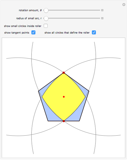
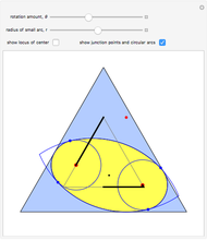
Snapshot 1: shows the case  ; then the roller becomes the intersection of two copies of a vesica pisces (a vesica pisces is the intersection of two congruent circles, where the center of each circle lies on the boundary of the other one—see the MathWorld entry for "Lens" (Wolfram MathWorld)); in this case the locus of the cusp is identical to the ambient pentagon
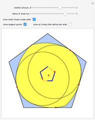
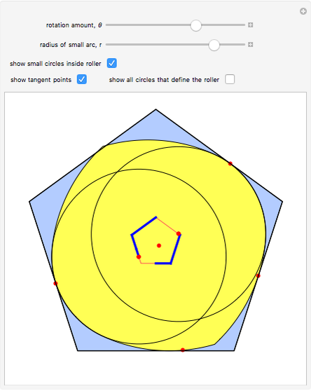
Snapshot 2: shows the case where  is large, and the locus is a rather small pentagon
Snapshot 3: shows the case of a small value of
The construction is based on an envelope construction similar to that in [1] to determine the proper radius  of the four large circular arcs. Once is known, the various junction points and angles that define the arcs are easily computed. It is critical that, for each orientation of the roller, its position within the large pentagon is determined. The red tangency points show that this rigidity holds, since there are always enough points of contact to prevent either up-down or left-right motion.
Reference:
[1] B. Cox and S. Wagon, "Mechanical Circle-Squaring," College Mathematics Journal, 40, 2009 pp. 238–247.
Permanent Citation
 Drilling a Triangular Hole
Barry Cox (University of Wollongong) and Stan Wagon (Macalester College)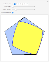 Drilling an n-Gon Hole for Odd n
Barry Cox and Stan Wagon (University of Wollongong and Macalester College)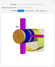 Square-Hole Drill in Three Dimensions
Stan Wagon (Macalester College)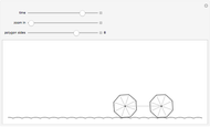 Roulette: A Comfortable Ride on an n-gon Bicycle
Borut Levart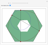 Drilling a Hexagonal Hole
Barry Cox (University of Wollongong, Australia) and Stan Wagon (Macalester College, USA)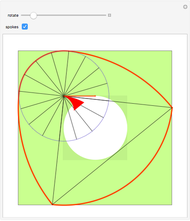 Drilling a Square Hole
Stan Wagon (Macalester College)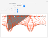 Regular Polygon Rolling on a Catenary
Michael Schreiber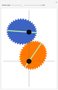 Elliptic Gears
Harry Calkins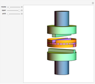 Oldham Coupling
Sándor Kabai Chebyshev's Lambda Mechanism
Nikita Panyunin
-
 Rolling Ball inside a Cylinder
Stan Wagon -
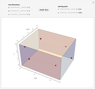 3D Billiard Loop in a Rectangular Box
Stan Wagon -
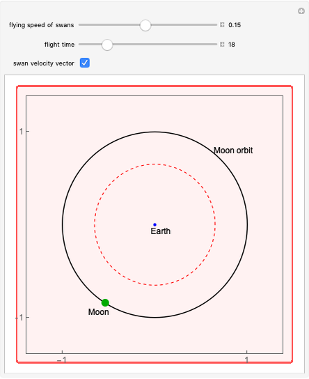 Flying to the Moon
Stan Wagon -
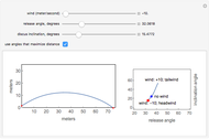 Discus Flight
Stan Wagon -
 Bicycle or Unicycle Tracks?
Stan Wagon -
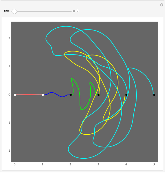
 Paths inside a Polygon
Stan Wagon -
 Penrose's Train Challenge
Stan Wagon -
 Bishop Edge Coloring
Stan Wagon -
 Simpson's Paradox
Stan Wagon -
 Regression Model with Transformations
Stan Wagon -
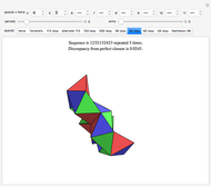
 Perfect 1-Factorizations of Graphs
Stan Wagon -
 The Banach-Tarski Paradox
Stan Wagon -
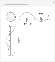 Spinning Out Sine and Cosine
Stan Wagon -
 Benford's Law and Data Spread
Stan Wagon -
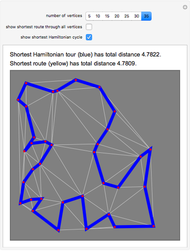 The Routing Problem
Stan Wagon -
 Solving Decanting Problems by Graph Theory
Stan Wagon -
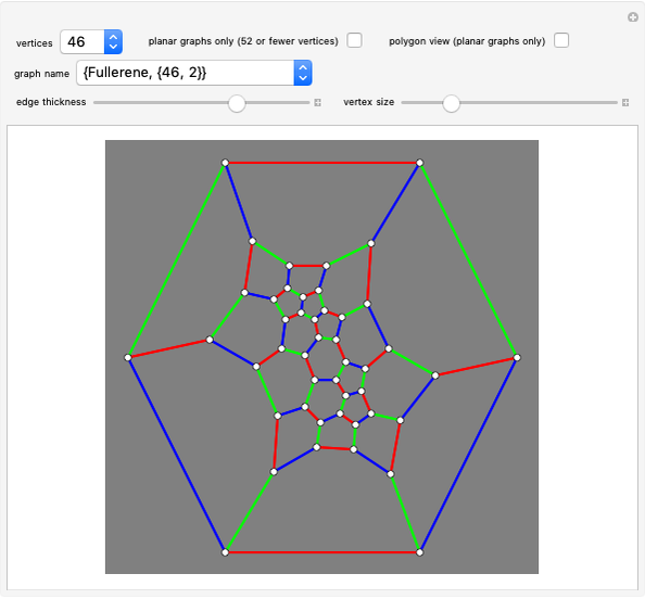
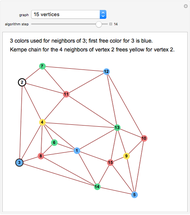 Four-Coloring Planar Graphs
Stan Wagon -
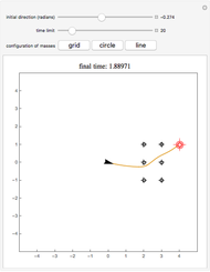 A Gravitational Optimization Problem
Stan Wagon -
 Tetrahedral Loops
Stan Wagon -
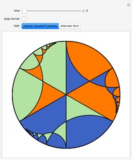
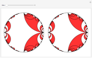 The Disappearing Hyperbolic Squares
Stan Wagon