Nowhere-Neat Tilings of the Plane


Requires a Wolfram Notebook System
Interact on desktop, mobile and cloud with the free Wolfram Player or other Wolfram Language products.
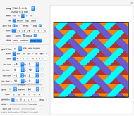
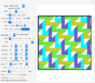
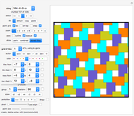
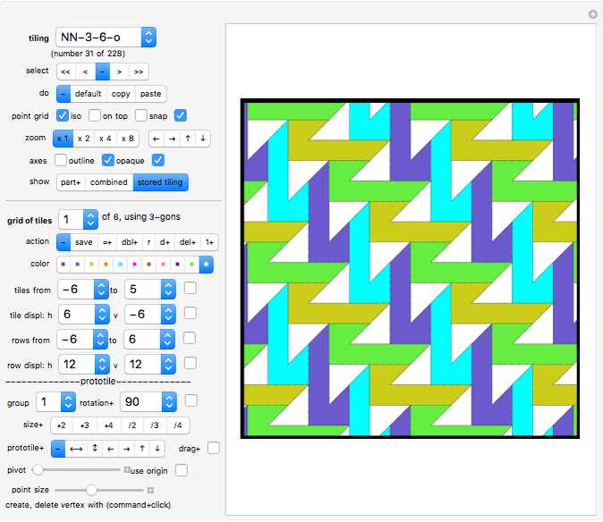
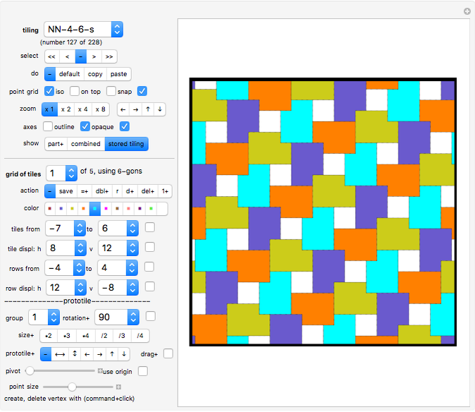
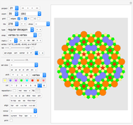
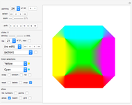
If no two tiles in a (polygonal) tiling have a full side in common, the tiling is called nowhere-neat.
[more]

Contributed by: Karl Scherer (October 2009)
Additional contributions by: Dave Walton
Open content licensed under CC BY-NC-SA
Snapshots
Details
Introduction
218 nowhere-neat tilings of the infinite plane using one or two prototiles are presented here. Some of these tilings and also some of the mathematical results quoted here have never been published before.
Only tilings on the integral grid are shown here. Hence all the vertices of all the tiles shown here have integral coordinates. (There are many more nowhere-neat tilings that cannot be positioned on the integral grid and that are not shown here.)
You can edit the given tilings or create your own. For this purpose ten identical tilings "Test1", …, "Test10" are listed at the end of the dropdown menu; you are invited to overwrite them with your own creations.
While the topic of this Demonstration is nowhere-neat tilings, it can be used to create any tilings on the orthogonal or isometric grid and hence is a useful tool for exploring such tilings in general. The system does not check whether a tiling is indeed nowhere-neat.
Scientific Results
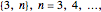
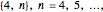
The following sets of one or two polygonal prototiles for nowhere-neat tilings of the plane have been found (the numbers denote the number of sides of the polygons):


Apart from tilings of the type there seems to be no solution for  if
if  .
.
For further information see the sister Demonstration "Nowhere-Neat Tilings of the Plane, Part 2", and also the author's book New Mosaics, referenced below, or the Zillions games Floor Tilings and Floor Tilings II.
Control: "select"
The options "<<", "<", ">", ">>" select the first, previous, next, and last stored tiling, respectively.
Control: "do"
Reset: Click "default" to restore the current tiling to its default. All editing information of this tiling will be lost.
Copy: Click "copy" to mark the current tiling. It will be used later by the "paste" option.
Paste: Click "paste" to paste the marked tiling to the current position, thereby replacing the current tiling.
Control: "point grid"
The "point grid" control contains four on/off buttons:
• The first button makes the integral lattice grid visible/invisible.
• The second button toggles between the ortho(gonal) grid and the iso(metric) grid. Note that changing the grid type can distort an existing tiling since the tiling data is based on counting grid increments: the unit of height in the orthogonal grid is 1, but in the isometric grid it is  . That is why the ortho/iso selection is always stored together with the tilings.
• The third button controls whether the grid is placed on top of or underneath the tiling.
• The fourth button controls whether the vertices should snap to the grid (i.e., whether they should have integral coordinates). The snap option only affects the prototile currently being edited. It does not affect any stored information. The snap setting is stored with the tilings.
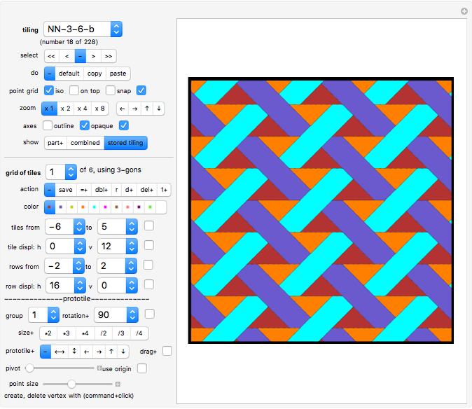
Control: "grid of tiles"
The tilings are constructed as a union of "tile grids". For each tile grid, a prototile is specified that is then copied to a grid of positions. All copies will carry the same color. In the given examples the grids never overlap. See below to find out how the grid of positions is specified.
The system stores the grid specifications rather than the data for each tile. Hence for each display the system recreates the tiling from the stored sets of its prototiles and the associated grid specifications.
Control: "zoom"
This control comes in handy when you create and edit the prototile of the current grid of tiles. When you have zoomed in you can shift the zoom window with the four arrow buttons next to the zoom options.
Control: "show"
"Show part+" will display only the selected grid of tiles (or—if group is greater than 0—the selected group of tile grids, starting with the current one). The current tile grid can then be edited. Click "store" to store the edited tile grid.
"Show combined" will enter the edit mode and display the stored tiling with the edited grid of tiles (combining the new part with the old parts). The old grid of tiles with the same number will not be shown. Click "store" to store the edited tile grid.
"Show stored tiling" will display the stored tiling, ignoring the editing of the current tile grid. While "show stored tiling" is selected the edit mode is switched off; hence you cannot use any of the "action" options.
If "show stored tiling" is active, selecting a new tile grid (or changing any other tile grid settings) will automatically switch to "show combined" and start the edit mode.
Control: "action"
Store: Click "store" to store your edited tile grid.
Double range: Click "dbl+" to create a copy of the current tile grid or a group of tile grids. The current grid will be saved first. The new grid(s) will be inserted at the next position(s) after the old group of tile grids. All the following entries will be renumbered. The system will update the tile grid number to display the number of the new tile grid. The new "current" grid will be the first grid of the newly copied set.
Reset: Click "reset" to reset the specifications of the currently selected tile grid to the last stored values.
Default range: Click "d+" to reset to default the specifications of the current grid and the next grids, the total number being given by the "group" selection. All editing information of these tile grids will be lost.
Delete range: Clicking "del+" will delete the current tile grid and also a few other tile grids with higher numbers (the number of elements in this group is given by the "group" drop-down menu). For technical reasons the last grid of a tiling cannot be deleted, hence "del+" does not work if all tile grids would be deleted.
Shuffle tile grids: Clicking option "1+" will shift a group of tile grids, beginning with the current one, to the start of the queue. This is a simple tool to shuffle the tile grids. The number of tile grids in the group is given by the "group" selection.
Color selection
Clicking a color starts the edit mode (if it is not yet active).
For purely aesthetic reasons the colors in the given tilings have been chosen so that no two adjacent tiles carry the same color. Of course having adjacent tiles always of different colors often means that more grids are necessary for the definition of the tiling.
For the condition of the tiling being nowhere-neat the choice of colors is irrelevant.
Controls: specification of grid positions
Clicking a specification of grid positions will start the edit mode (if it is not yet active).
A grid of positions (for the copies of the given prototile) is specified as follows:
The tile displacements ("tile displ") show how far the next tile is from the previous tile in the same row of tiles (h: horizontal displacement; v: vertical displacement).
The "from" and "to" entries define where the row starts and ends. (If a row extends beyond the screen frame it usually means that it should go on forever.)
The row displacements ("row displ") show the displacement between one row and the next. Again, the "from" and "to" entries define how many rows there are to be displayed.
Note that the prototile itself and the row containing the prototile have the number 0, since the entries "from" and "to" define how many steps away the start and end of the row are!
Some tilings contain "tile grids" that consist only of one tile, a few tiles, or a single row of tiles.
After the controls there is a tick box. Clicking it (in edit mode) will set the two associated controls to zero (after putting them in temporary storage). If you click it when both controls are zero, then the values will be restored from temporary storage.
Changing any tile grid parameter automatically invokes the edit mode (if it is not active already).
Editing the prototile
Start the edit mode (for example by selecting "show part" or "show combined"). You will see a polygon whose vertices are marked by large dots. This is the "prototile" of your tile grid.
The prototile determines what all the tiles in the grid will look like. Click the color setter bar to change the color of the prototile. Move the vertices to change the shape of the prototile. If you have this selected, the vertices of your prototile will snap to the integral orthogonal grid.
You can add a vertex with Alt-click in Windows or Option-click on the Mac.
After moving the cursor to a marked vertex you can delete a vertex (again with Alt-click or Option-click).
Control: "group"
Here you decide how large the group of tile grids is that you want to manipulate simultaneously. The group of tile grids begins with the current one.
All controls which carry a plus sign "+" are able to affect a whole group of tile grids at once. These are : show part ("part+"), save from-to parameters ("=+"), double ("dbl+"), reset ("reset+"), default ("d+"), delete ("del+"), move to first in sequence ("1+"), all shift and mirror controls for prototiles (" ","↕","←","
 ","↑","↓"), rotation ("rotation+"), and drag ("drag+").
Control: rotate prototile or prototile group
Select a rotation from the drop-down menu, then activate it by clicking the checkbox next to it. You can click the checkbox several times in a row (but give the system time to react in between).
If group > 1 is selected, any rotation will affect a group of tile grids, beginning with the current one. This way you can rotate groups of prototiles around the same point. (Note that this does not rotate the resulting tiling!) All changes will be immediately saved, so you do not have to click the "save" button afterwards.
If pivot > 0 , the rotation will be around the selected vertex; otherwise the group will rotate around the center of the group. If "use origin" is selected, the origin is used as the fixed point for the rotation.
Control: resize prototile or prototile group
Click one of the "size+" options to resize your prototile. If "pivot > 0" is selected the fixed point of the resizing will be the selected vertex; otherwise the fixed point will be the center of the prototile.
If the group > 0 is selected, resizing will affect a group of tile grids, beginning with the current one. All changes will be immediately saved, so you do not have to click the "save" button afterwards.
If pivot > 0 is selected the fixed point of the resizing will be the selected vertex; otherwise the fixed point will be the center of the prototile. If "use origin" is selected, the origin is used as the fixed point for resizing.
Control: process prototile or prototile group
The options of the setter bar allow you flip the prototile horizontally ("") or vertically ("↕") or shift it in one of four directions ("←","","↑","↓").
If the group > 1 is selected, the shift and mirror operations will affect a group of tile grids, beginning with the current one. All changes will be immediately saved, so you do not have to click the "save" button afterwards.
If pivot > 0 is selected the fixed point of the mirroring will be the selected vertex; otherwise the fixed point will be the center of the group of prototiles. If "use origin" is selected, the axes are used for mirroring.
Control: drag prototile or prototile group
Clicking the drag button starts a drag mode, which then stays active until the button is clicked again. In drag mode the whole prototile moves anywhere you want it. Just click the target position or drag a vertex. If pivot = 0, the closest vertex will be moved to the designated position. Otherwise the selected vertex will be moved to the designated position.
If the group > 1 is selected, the drag operation will affect a group of tile grids, beginning with the current one. All changes will be immediately saved, so you do not have to click the "save" button afterwards.
Control: "pivot"
Here you can select a pivot (a handle) for your rotation, flip, and drag operations. Moving the slider will cause one of the prototile's vertices to turn gray. This vertex will then be used by the rotate, flip, and drag processes mentioned above.
If pivot = 0 (which is the default), then the axes and their intersection point will be used for the rotate and flip processes. If "use origin" is selected, the origin is used as the fixed point for the rotations and mirroring.
Note
If many polygons are displayed the system can be slow to react to your input. If a click does not have an effect, click another button first (click a neutral "-" button), then go back to your previous click. Give the system time to react!
Some deeper mathematical results
The following theorems are taken from the author's book New Mosaics.
The existence theorem for nowhere-neat tilings
In general it is not known whether a nowhere-neat tiling of type  exists for a given pair
  of natural numbers, even if we allow any number of prototiles. Hence there is no general existence theorem for nowhere-neat tilings. However, one can prove a less general version stating that for any natural numbers
  there are nowhere-neat tilings of the plane of types
  ,
,  , and
, and  . In detail:
Given  numbers
  , the following holds (if any number of prototiles is allowed per type):
a. There are nowhere-neat tilings of the plane of types ,  , and .
b. For the minimum number of prototiles, these are the upper bounds:
 and especially:
  .
.
 and especially:
  .
.
 and especially:
  .
.
The extension theorem for nowhere-neat tilings
Let  be a finite nowhere-neat tiling that is totally surrounded by a polyline
  (i.e., by an outline of a polygon) without touching it. Then can be extended to a nowhere-neat tiling of . The extension can be chosen to consist only of triangles and quadrilaterals.
Corollaries
Any nowhere-neat tiling can be extended to a nowhere-neat tiling of the whole plane.
For any polygon there is a nowhere-neat tiling of a square that contains as one of its tiles.
For any polygon there is a nowhere-neat tiling of the plane that contains as one of its tiles.
References
The second half of the book New Mosaics, privately published in 1997 by this author, investigates the topic of nowhere-neat tilings in detail. Many more examples are presented there than in this Demonstration.
The Zillions games Floor Tilings and Floor Tilings II by this author deal with the same topic. Floor Tilings deals with nowhere-neat tilings of the plane on the orthogonal grid and Floor Tilings II deals with nowhere-neat tilings of the plane on the isometric grid.
Most tilings were found by the author. Dave Walton contributed solutions for the cases  ,
,  . It is easy to construct them from the tilings NN-4-9 and NN-4-13 shown in this Demonstration.
Note
With many polygons displayed, the system can be slow to react to your input. If a click does not have an effect, click another button first, then go back to your previous click. Give the system time to react!
Permanent Citation
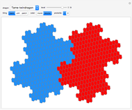 Tiling Dragons and Rep-tiles of Order Two
Dieter Steemann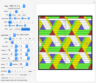 Nowhere-Neat Tilings of the Plane, Part 2
Karl Scherer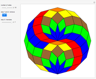 Dissecting a Regular 2n-gon into Four Smaller 2n-gons
Izidor Hafner Gailiunas's Spiral Tilings
Dieter Steemann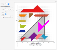 Nowhere-Neat Tilings
Karl Scherer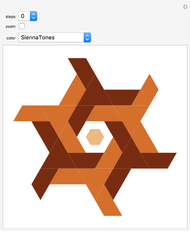 Recursively Defined Partial Tilings of the Plane
Enrique Zeleny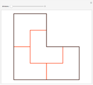 Rep-Tile
Eric W. Weisstein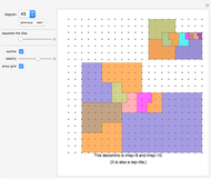 Irreptiles
Karl Scherer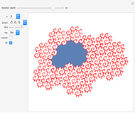 Kenyon Tiling Construction (Boundary)
Dieter Steemann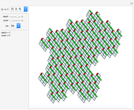 Kenyon Tiling Construction (Substitution)
Dieter Steemann
-
 Polyhedral Playground
Karl Scherer -
 Tiling Constructor, Tile-Dragging Variant
Karl Scherer -
 The Catenax Puzzle
Karl Scherer -
 Angel Puzzle
Karl Scherer -
 Constructing and Manipulating Graphs
Karl Scherer -
 3D Construction Set
Karl Scherer -
 Blended Quadrilaterals
Karl Scherer -
 Rotating Polyhedra in Space
Karl Scherer -
 The Misdirection Game
Karl Scherer -
 Tensegrity
Karl Scherer -
Nowhere-Neat Tilings
Karl Scherer -
 Pocket Calculator
Karl Scherer -
 Area Puzzle
Karl Scherer -
 Molecule Construction Set
Karl Scherer -
 The Ray Puzzle
Karl Scherer -
 Animated Model of an Industrial Robot Arm
Karl Scherer -
 Model of an Industrial Robot Arm
Karl Scherer -
 Color-Blended Circular Tiles
Karl Scherer -
 Rep-Tiles
Karl Scherer -
 Armed Balloons Puzzle
Karl Scherer